Exhaust gas diffuser for a gas turbine and a method for operating a gas turbine that comprises such an exhaust gas diffuser

一种燃气轮机、扩散器的技术,应用在用于弹性流体的泵送装置的部件、机器/发动机、液体燃料发动机等方向,能够解决燃气轮机和加力燃烧室组合运行限制等问题,达到避免空气动力学损失、改进效率的效果

Inactive Publication Date: 2013-03-27
SIEMENS AG
View PDF8 Cites 1 Cited by
  • Summary
  • Abstract
  • Description
  • Claims
  • Application Information

AI Technical Summary

Problems solved by technology

This leads to backfiring even with the afterburner installed there, whereby the combined operation of the gas turbine and afterburner is strongly limited

Method used


Image

  • Exhaust gas diffuser for a gas turbine and a method for operating a gas turbine that comprises such an exhaust gas diffuser
  • Exhaust gas diffuser for a gas turbine and a method for operating a gas turbine that comprises such an exhaust gas diffuser
  • Exhaust gas diffuser for a gas turbine and a method for operating a gas turbine that comprises such an exhaust gas diffuser

Examples


Embodiment Construction

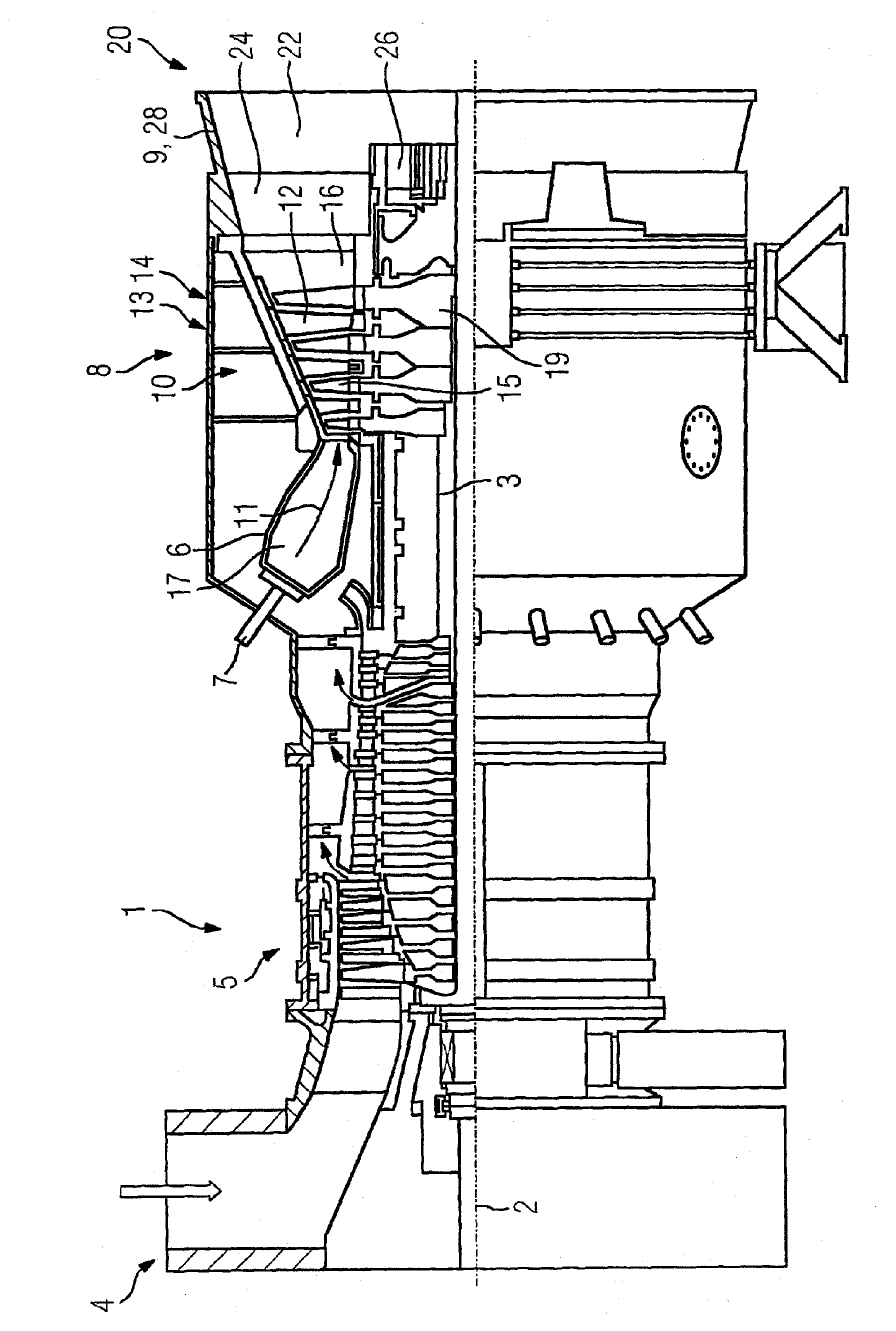
[0027] figure 1 A partial longitudinal section of the gas turbine 1 is shown. The gas turbine has an internally mounted rotor 3 rotatable about a machine axis 2 , which is also referred to as a turbine rotor. Along the rotor 3 there are an intake housing 4 , a compressor 5 , an annular annular combustion chamber 6 with burners 7 arranged rotationally symmetrically to one another, a turbine unit 8 and an exhaust housing 9 . The annular combustion chamber 6 surrounds a combustion chamber 17 which communicates with an annular hot gas channel 16 . There, four successively connected blade stages 10 form the turbine unit 8 . Each blade stage 10 is formed by two blade rings. Viewed in the direction of flow of the hot gas 11 generated in the annular combustion chamber 6 , the row 14 of rotor blades 15 each follows the row 13 of guide blades in the hot gas channel 16 . The guide blades 12 are fastened to the stator, whereas the rotor blades 15 of the rows 14 are each attached to th...


PUM


Abstract

The invention relates to an exhaust gas diffuser (20) for a gas turbine (1) having an annular outer wall (28) for guiding the diffuser flow (30) and in which an annular guiding element (32), arranged concentrically to said outer wall (28), is provided to influence the diffuser flow (30). In order to improve the aerodynamic effect of the exhaust gas diffuser (20) and to adapt this simultaneously and in an optimal manner for a plurality of operational gas turbine states, it is suggested that the guiding element (32) has a surface (34) which is radially directed inwards and which has a circumferential contour that is convex in the longitudinal section so as to form a displacement element, and that the guiding element (32) is axially displaceable between two positions such that said guiding element (32), when in a first position, allows a flow between the guiding element (32); and outer wall (28) and, when in a second position, largely prohibits a flow between the guiding element (32) and outer wall (28). In addition, the invention discloses a method for operating a gas turbine (1) in which, in order to reduce aerodynamic losses and to increase pressure recovery, the guiding element (32) is displaced in the direction of the second position or until in said second position as the mass flow increases and / or the guiding element (32) is displaced in the direction of the first position or until in said first position as the mass flow reduces.

Description

technical field [0001] The invention relates to an exhaust gas diffuser for a gas turbine having an annular outer wall for guiding a diffuse flow, in which an annular guide element arranged concentrically to the outer wall for influencing the diffuse flow is arranged. . Furthermore, the invention relates to a method for operating a gas turbine having an exhaust gas diffuser of the type described. Background technique [0002] Gas turbines and exhaust diffusers for such gas turbines are known from the prior art for a long time. Exhaust diffusers with relatively large opening angles of 10° and more are known, for example, from DE 198 05 115 A1. The exhaust gas diffuser achieves a large opening angle by providing, in the center of the diffuser channel, a guide extending in the axial direction for extending the otherwise short gas turbine hub. The exhaust diffuser is formed as a ring diffuser by using guide bodies. As a result, a larger area of ​​the recirculation zone behin...

Claims


Application Information

Patent Timeline
Patent Type & Authority Applications(China)
IPC IPC(8): F01D9/02F01D17/14F01D25/30
CPCF01D9/02F01D17/141F04D29/54F05B2250/711F05D2250/711F05D2250/324F01D25/30
Inventor 马克·布勒克托比亚斯·布哈尔
Owner SIEMENS AG
Why Eureka
Try Eureka