
Wheel grip factor estimation apparatus

a factor estimation and factor technology, applied in the direction of machinery control, process and machine control, instruments, etc., can solve the problems of vehicle speed not being reduced sufficiently by those controls, and not being able to prevent vehicles

Inactive Publication Date: 2005-05-17
AISIN SEIKI KK +2
View PDF17 Cites 48 Cited by
  • Summary
  • Abstract
  • Description
  • Claims
  • Application Information

AI Technical Summary

Benefits of technology

[0014]Accordingly, it is an object of the present invention to provide a wheel grip factor estimation apparatus for estimating a grip factor indicative of a grip level of tire in a lateral direction to a wheel accurately.
[0015]It is another object of the present invention to provide a vehicle motion control apparatus having the grip factor estimation apparatus for estimating the grip factor accurately, and controlling a motion of the vehicle appropriately on the basis of the grip factor, when the grip factor is reduced less than a predetermined value.
[0027]Preferably, a vehicle motion control apparatus includes the apparatus for estimating the grip factor as described above, and further includes control means for controlling at least one of braking force, engine output and shift position of the vehicle at least in response to the state variable detected by the vehicle state variable detection means. And, the control means is adapted to control at least one of the braking force, engine output and shift position of the vehicle when the grip factor estimated by the grip factor estimation means becomes less than a predetermined value, to reduce a speed of the vehicle.

Problems solved by technology

However, as the controls begin at the cornering limit, the vehicle speed may not be reduced sufficiently by those controls.
Therefore, it might be caused that the vehicle can not be prevented only by those controls from being forced outside of the curve.

Method used


Image

  • Wheel grip factor estimation apparatus
  • Wheel grip factor estimation apparatus
  • Wheel grip factor estimation apparatus

Examples


Embodiment Construction

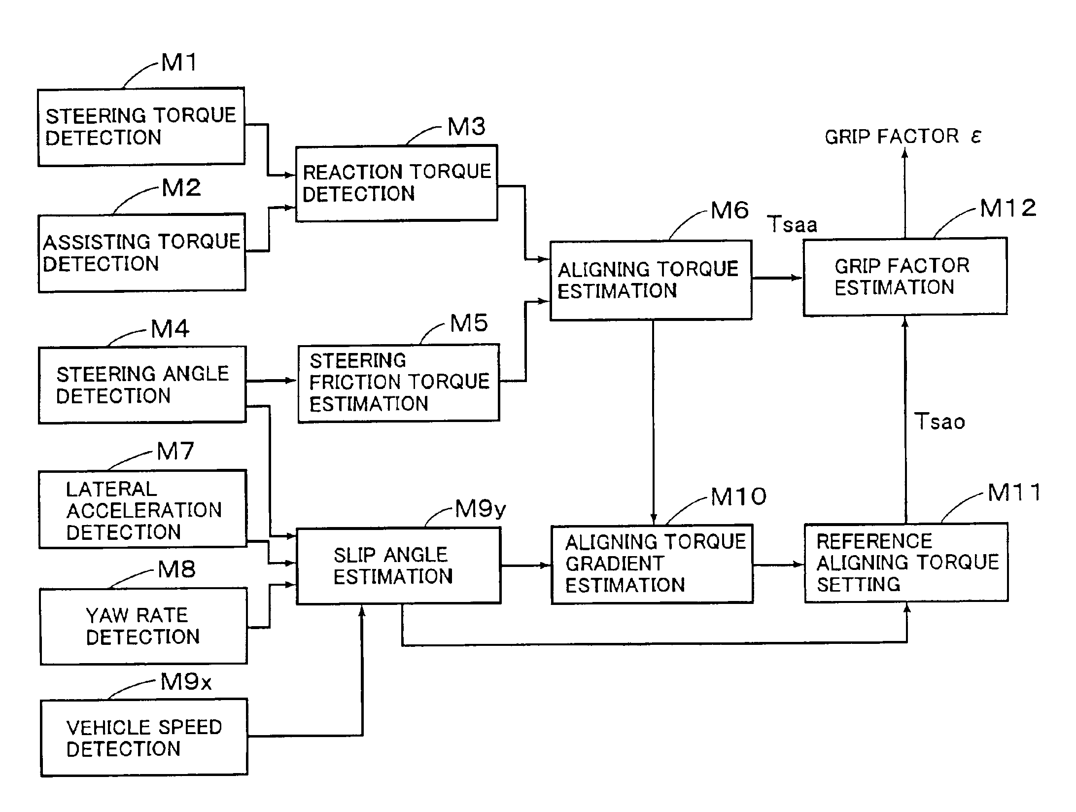
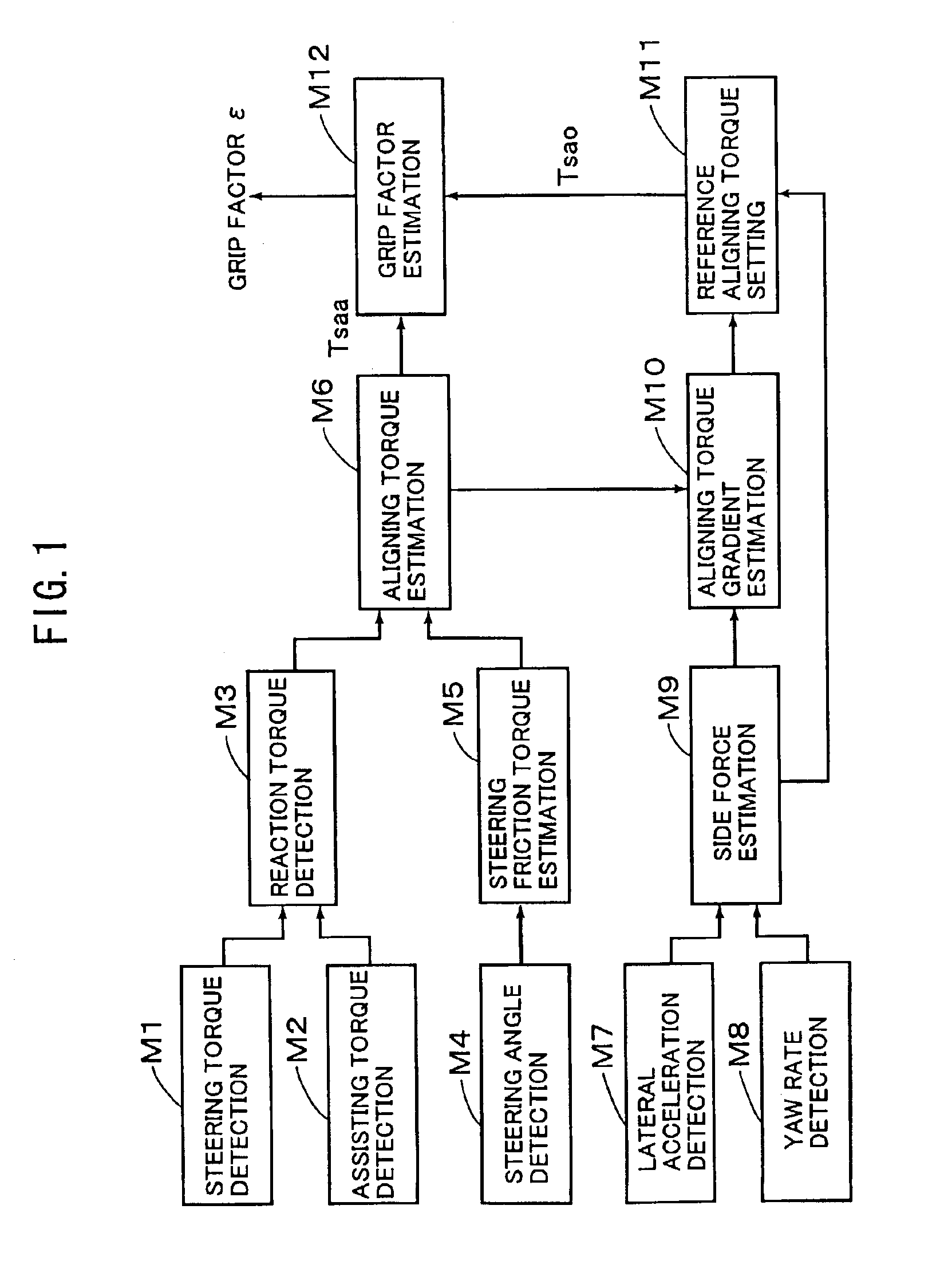
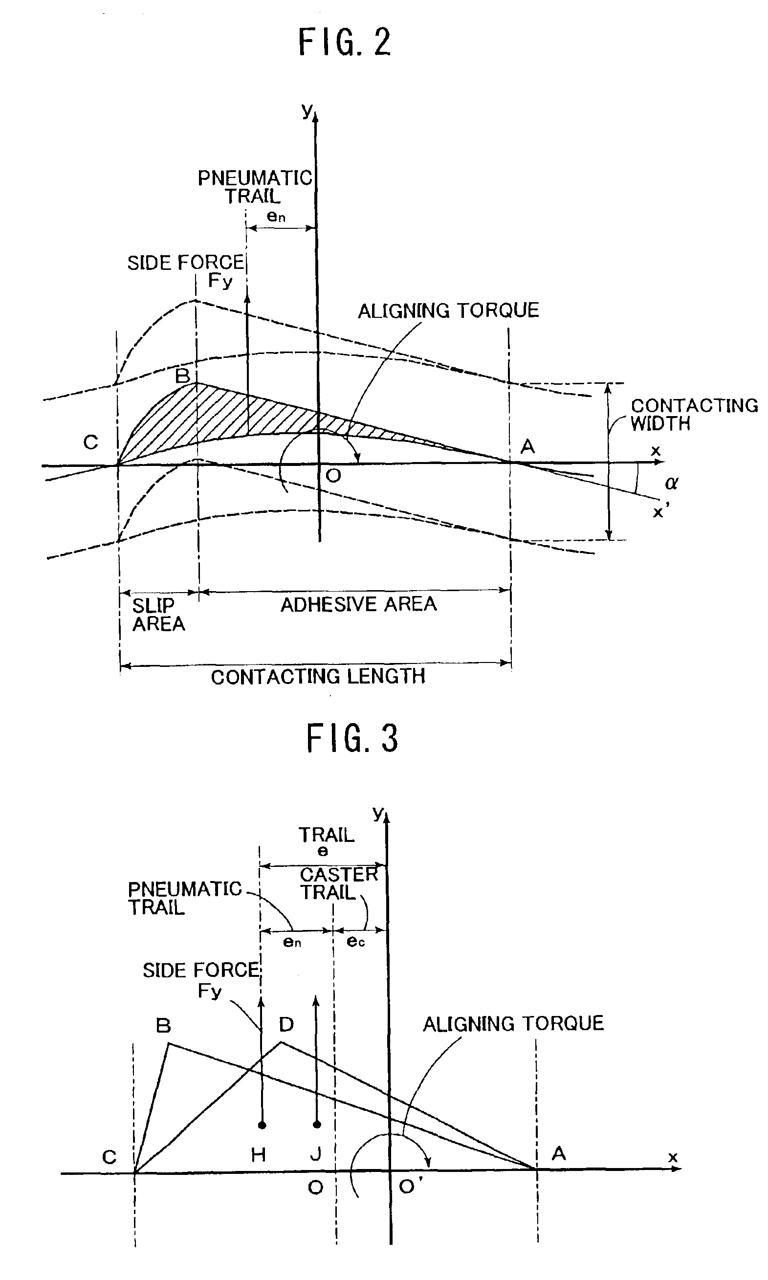
[0083]Referring to FIG. 1, there is schematically illustrated a wheel grip factor estimation apparatus according to an embodiment of the present invention. FIG. 1 illustrates a block diagram of the grip factor estimation apparatus for estimating the grip factor on the basis of the side force and aligning torque. At the outset, an example of estimating the grip factor with reference to FIGS. 2-4.

[0084]As explained heretofore referring to FIGS. 2 and 3, the characteristic of the aligning torque to the side force of the front wheel will be the one as indicated by Tsaa in FIG. 4. In this case, when the actual aligning torque is indicated by Tsaa and the side force of the front wheel is indicated by Fyf, the actual aligning torque Tsaa can be given by Tsaa=Fyf·(en+ec), wherein a nonlinear characteristic of the actual aligning torque Tsaa to the front side force Fyf indicates a linear variation of the pneumatic trail en. Therefore, a gradient K1 of the actual aligning torque Tsaa to the f...


PUM


Abstract

The present invention is directed to a wheel grip factor estimation apparatus, which includes a steering factor detection unit for detecting at least one of steering factors including a steering torque and steering effort applied to a steering system extending from a steering wheel to a suspension of a vehicle, an aligning torque estimation unit for estimating an aligning torque produced on at least a wheel of the vehicle on the basis of the steering factor detected by the steering factor detection unit, and a vehicle state variable detection unit for detecting a state variable of the vehicle. The apparatus further includes a wheel factor estimation unit for estimating at least one of wheel factors including a side force and slip angle applied to the wheel on the basis of the vehicle state variable, and a grip factor estimation unit for estimating a grip factor of at least a tire of the wheel, in accordance with a relationship between the estimated alignment torque and the estimated wheel factor.

Description

[0001]This application claims priority under 35 U.S.C. Sec. 119 to No.2002-120555 and No.2002-120566 filed in Japan on Apr. 23, 2002, respectively, the entire contents of which are herein incorporated by reference.BACKGROUND OF THE INVENTION[0002]1. Field of the Invention[0003]The present invention relates to a wheel grip factor estimation apparatus, particularly relates to an apparatus for estimating a grip factor indicative of a grip level of tire on a road surface in a lateral direction of a vehicle wheel.[0004]2. Description of the Related Arts[0005]In order to maintain a stability of a vehicle, there is known heretofore an apparatus for controlling a braking force applied to each wheel on the basis of vehicle state variable detected and determined, as disclosed in Japanese Patent Laid-open Publication No.6-99800, for example. In this publication, a target value of yaw rate is provided on the basis of a vehicle speed and a steering angle, and an over steering or an under steerin...

Claims


Application Information

Patent Timeline
IPC IPC(8): B60G17/015B60G17/0195B60T8/17B60T8/172B60W30/02B60W40/06
CPCB60G17/0195B60K41/282B60T8/172B60W30/02B60W40/064B60W40/101B60W2900/00B60G2400/106B60G2400/822B60G2800/24B60G2800/702B60G2800/95B60K2741/283B60T2210/12B60W2050/0028B60W2510/20B60W2510/22B60W2520/125B60W2520/14B60W2520/20B60W2530/20B60W2550/148B60G2400/0523B60W2552/40
Inventor YASUI, YOSHIYUKITANAKA, WATARUONO, EIICHIMURAGISHI, YUJIASANO, KATSUHIROMOMIYAMA, MINEKAZUOGAWA, SYOJIASANO, KENJIIMOTO, YUZOKATO, HIROAKI
Owner AISIN SEIKI KK
Learn More