Wire management grommet

a technology of wire management and grommets, which is applied in the direction of insulating bodies, coupling device connections, furniture parts, etc., can solve the problems of limiting the number of cables or wires which can be fed through, cables may terminate, and small objects can easily fall through, so as to achieve sufficient mechanical stiffness, effective friction engagement, and low cost

Inactive Publication Date: 2005-05-24
CUSTOM PLASTIC INC AN ILLINOIS
View PDF7 Cites 23 Cited by
  • Summary
  • Abstract
  • Description
  • Claims
  • Application Information

AI Technical Summary

Benefits of technology

[0014]It is yet a further objective of the invention to provide a wire management grommet which can be inexpensively manufactured.
[0015]In light of the above, the applicants propose a wire management grommet which can be seated in a cooperating bore or aperture in a desk or table top to provide effective distribution of plural disparate cable and wire combinations. The wire management grommet includes an outer peripheral member and an inner perforate member. The outer peripheral member is constructed and arranged to frictionally engage a planar surface, usually a desk or tabletop. The outer peripheral member is formed from a first rigid material having sufficient mechanical stiffness for effective frictional engagement with the planar surface and the cooperating aperture. The inner perforate member is formed from a second flexible material and is overmolded using conventional injection molding techniques to the said outer peripheral member to form a unitary grommet. The second flexible material is chosen to have sufficient flexibility to permit passage of disparate cable combinations through the inner perforate member.

Problems solved by technology

Clearly, a drawback of having such an open aperture is that small objects can easily fall through.
Another drawback of some of the prior art designs including hinged cover portions is that the size of the wire-receiving opening is much smaller than the overall grommet, thus limiting the number of cables or wires which can be fed through.
Another problem with having a relatively small wire-receiving opening is that the cables may terminate in large connector elements (e.g. A / C plugs or serial port connectors) which are too large to fit through the opening.
If the star-like pattern were punctured or torn to accommodate cables, the wedge portions would serve to somewhat close the opening around the cables, however, these wedge portions would tend to become randomly splayed around the cables, resulting in an untidy appearance.
Also, if multiple cables were used, the star design would tend to position all the cables together in the center, which could result in electrical interference between the electronic devices.
If the circles were punched out to provide the alternative mode of use, it would provide the desired amount of separation between the cables, however it would not be possible to insert larger connector elements through the grommet.
Another disadvantage of this design is that once the punch-out portions are removed in the desired pattern for one particular set of cables, the grommet cannot be used again for another cable arrangement requiring a different punch-out configuration.

Method used


Image

  • Wire management grommet
  • Wire management grommet

Examples


Embodiment Construction

[0019]Although the invention will be described in terms of a specific embodiment, it will be readily apparent to those skilled in this art that various modifications, rearrangements, and substitutions can be made without departing from the spirit of the invention. The scope of the invention is defined by the claims appended hereto.

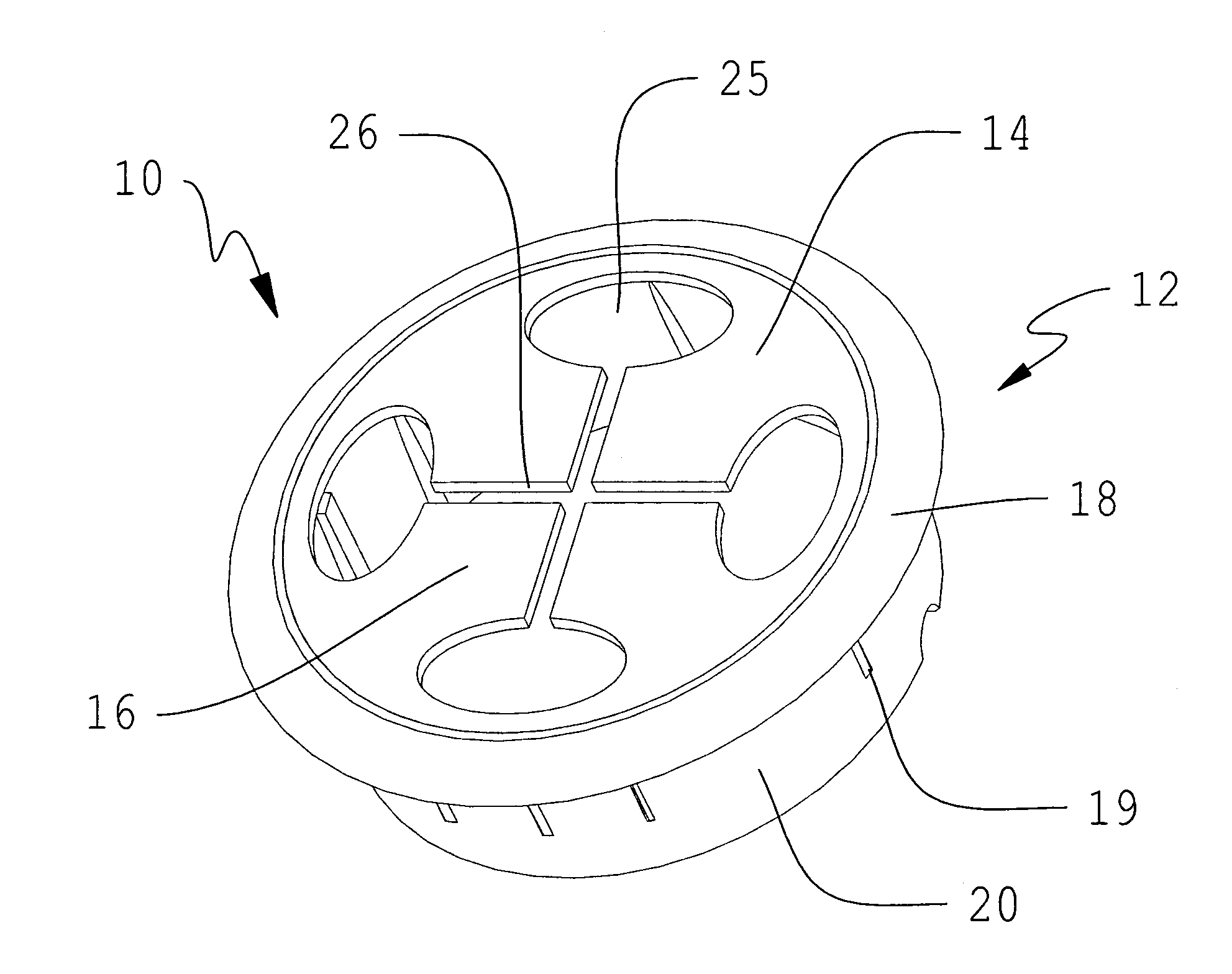
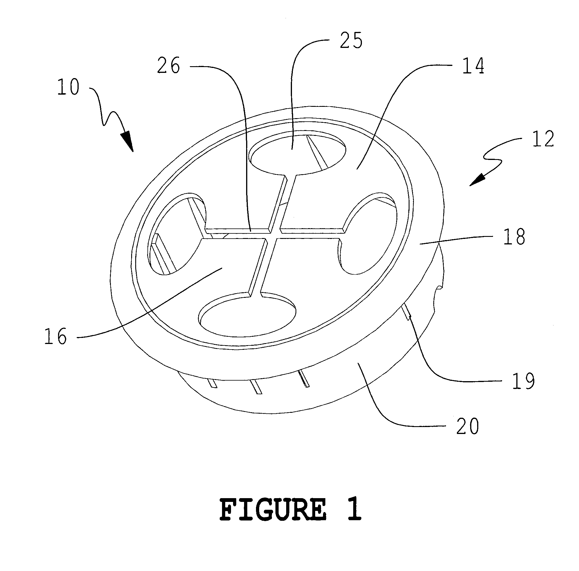
[0020]FIG. 1 illustrates a wire management grommet 10 according to a preferred embodiment of the invention. In use, the wire management grommet 10 is seated in a cooperating bore or aperture in a desk or table top. The wire management grommet 10 of the invention provides effective distribution of plural disparate cable and wire combinations as are present, for example, at a computer workstation.

[0021]The wire management grommet 10 includes an outer peripheral member 12 and an inner perforate member 14. The outer peripheral member 12 is constructed and arranged to frictionally engage a planar surface, usually a desk or tabletop. The outer peripheral member ...


PUM


Abstract

A wire management grommet includes an outer peripheral member and an inner perforate member. The outer peripheral member is constructed and arranged to frictionally engage a planar surface, usually a desk or tabletop. The outer peripheral member is formed from a first rigid material having sufficient mechanical stiffness for effective frictional engagement with the planar surface and the cooperating aperture. The inner perforate member is formed from a second flexible material and is overmolded using conventional injection molding techniques to the said outer peripheral member to form a unitary grommet. The second flexible material is chosen to have sufficient flexibility to permit passage of disparate cable combinations through the inner perforate member. The inner perforate member has a plurality of radially dispersed openings constructed and arranged for strain-free engagement of a plurality of cables so that the said inner perforate member returns to its original configuration after the cables have been inserted therethrough.

Description

FIELD OF THE INVENTION[0001]This invention is related to grommets for guiding electrical wiring through desk tops, or the like, and in particular to a grommet configured to position and organize a plurality of various types of wires within the grommet aperture, while providing tight closure thereof.BACKGROUND OF THE INVENTION[0002]Desktop workstations in an office environment are usually furnished with electrical devices such as personal computers, telephone equipment, power supply units, etc. which require cable connections to A / C outlets and / or telephone jacks. A typical computer system can include the CPU tower, monitors, a mouse, a keyboard, speakers, and any number of other peripheral devices, each including wire or cable connection means. To accommodate this multitude of wires and cables associated with workstations, modern office furniture often includes an aperture or bore in the desktop which allows the wires and cables to be fed through so that they are relatively unobtrus...

Claims


Application Information

Patent Timeline
Patent Type & Authority Patents(United States)
IPC IPC(8): F16L5/00H02G3/22H02G3/08
CPCH02G3/083A47B2200/0082Y10T16/063Y10T16/05Y10T16/088
Inventor TISBO, PETER M.
Owner CUSTOM PLASTIC INC AN ILLINOIS
Why Eureka
Try Eureka