Four-wheel drive control system and method

a control system and four-wheel drive technology, applied in mechanical equipment, transportation and packaging, tractors, etc., can solve the problems of never ending slipping or spinning of the main driving wheels, and achieve the effect of improving control responsiveness

Inactive Publication Date: 2005-05-24
HITACHI LTD
View PDF18 Cites 6 Cited by
  • Summary
  • Abstract
  • Description
  • Claims
  • Application Information

AI Technical Summary

Benefits of technology

[0007]It is accordingly an object of the present invention to provide a four-wheel drive control system that is capable of improving the control responsiveness while being capable of preventing a control hunting of repeating a control of increasing a driving force to be distributed to auxiliary driving wheels and a control of decreasing the same alternately.

Problems solved by technology

For this reason, the above-described four-wheel drive control system encounters a problem that a control hunting that will be described later occurs at running on a low friction road (hereinafter referred to as low-μ road), climbing, acceleration, etc.
In such a case, there occurs a problem that the slip or spin of the main driving wheels is never ended.

Method used


Image

  • Four-wheel drive control system and method
  • Four-wheel drive control system and method
  • Four-wheel drive control system and method

Examples


first embodiment

[0021](First Embodiment)

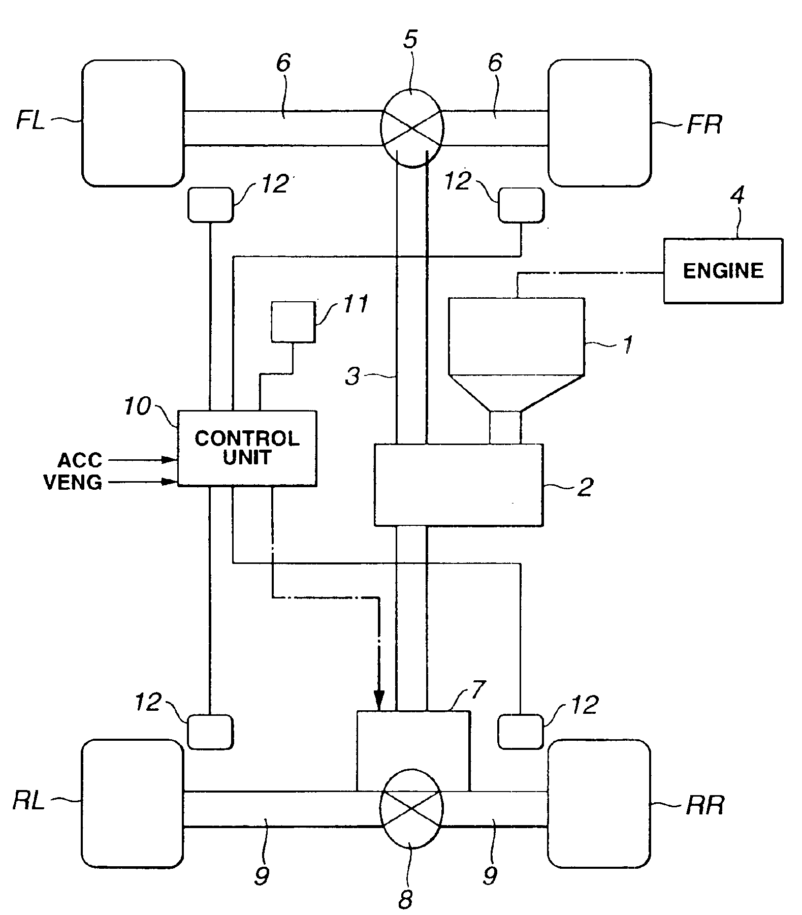
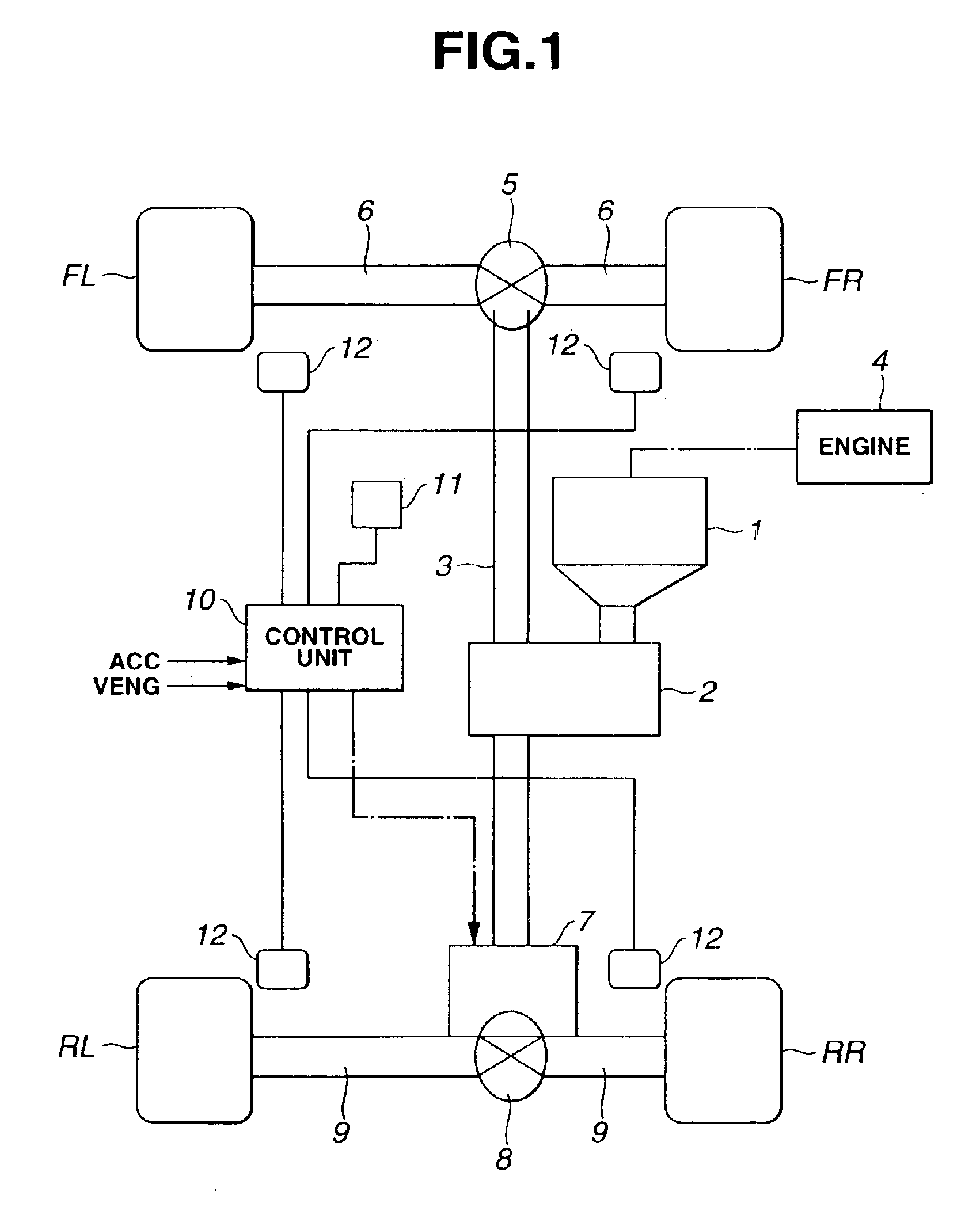
[0022]Referring first to FIG. 1, a transmission is indicated by 1 and drivingly connected to internal combustion engine 4 serving as a power source. A driving force from engine 4 is transmitted to transfer 2 after being changed in rotational speed as desired by transmission 1. In the meantime, power source 4 is not limited to an internal combustion engine but can be an electric motor or the like.

[0023]Transfer 2 transmits a driving force from transmission 1 to output shaft 3. The driving force transmitted to output shaft 3 is always transmitted to left and right front wheels FL, FR by way of front differential gear 5 and drive shafts 6. When friction clutch 7 is engaged, the driving force transmitted to output shaft 3 is transmitted to left and right rear wheels RL, RL by way of rear differential gear 8 and drive shafts 9.

[0024]Clutch 7 changes a rear wheel or auxiliary driving wheel driving force distribution ratio, i.e., a ratio of the driving force to be d...

second embodiment

[0058](Second Embodiment)

[0059]Second embodiment will now be described. Since the basic structure of the second embodiment is substantially similar to that of the first embodiment, description thereto is omitted for brevity and description will be made only to a driving force distribution control that is different from that of the first embodiment.

[0060]FIG. 7 is a flowchart of a driving force distribution control in the four-wheel drive control system of the second embodiment.

[0061]In step S701, a rear wheel speed VWR is obtained. In the meantime, the rear wheel speed VWR is obtained from an average of the wheel speeds VWRR, VWRL of rear wheels RR, RL, i.e., obtained from:

VWR=(VWRR+VWRL) / 2

[0062]Further, in step S702, a front wheel speed VWF is obtained from wheel speeds VWFR, VWFL of front wheels FR, FL.

[0063]Then, in steps S703 to S705, the dummy vehicle body speed VFF is obtained on the basis of the judgment on whether the vehicle is in an accelerated or decelerated state.

[0064]N...


PUM


Abstract

A four-wheel drive control system is provided which comprises a driving force distribution mechanism for transmitting a driving force from a power source to main driving wheels of a vehicle and capable of distributing the driving force to auxiliary driving wheels of the vehicle, a rotational speed difference detector for detecting a rotational speed difference between the main and auxiliary driving wheels, and a driving force distribution controller for controlling a distribution of the driving force to the main and auxiliary driving wheels on the basis of the rotational speed difference, wherein the driving force distribution controller determines a driving force to be transmitted to the auxiliary driving wheels on the basis of an output of the power source, a longitudinal load distribution in the vehicle and the rotational speed difference. A four-wheel drive control method is also provided.

Description

BACKGROUND OF THE INVENTION[0001]The present invention relates to a four-wheel drive control system and method for controlling a distribution of a driving force between main and auxiliary driving wheels (e.g., front and rear wheels) of a vehicle by controlling a driving force distribution mechanism in accordance with a rotational speed difference between the main and auxiliary driving wheels.[0002]It has heretofore been proposed a four-wheel drive control system that controls a driving force distribution between front and rear wheels (e.g., main and auxiliary driving wheels) by controlling a driving force distribution mechanism in accordance with a rotational speed difference between the front and rear wheels.[0003]Such a four-wheel drive control system is adapted to judge that a slip or spin of the main driving wheels is caused to obstruct start or acceleration of the vehicle when a rotational speed difference between the front and rear wheels becomes large and increase a driving f...

Claims


Application Information

Patent Timeline
Patent Type & Authority Patents(United States)
IPC IPC(8): B60K28/16B60K23/08B60K17/35F16D48/12
CPCB60K23/0808B60K28/16B60W40/13B60W2550/142B60W2520/28B60W2530/10B60W2530/16B60W2520/105B60W2552/15
Inventor OHTSU, NOBUYUKI
Owner HITACHI LTD
Why Eureka
Try Eureka