

Electromagnetic fuel injection valve and method for manufacturing same
- Summary
- Abstract
- Description
- Claims
- Application Information
AI Technical Summary
Benefits of technology
Problems solved by technology
Method used
Image

Examples
Embodiment Construction
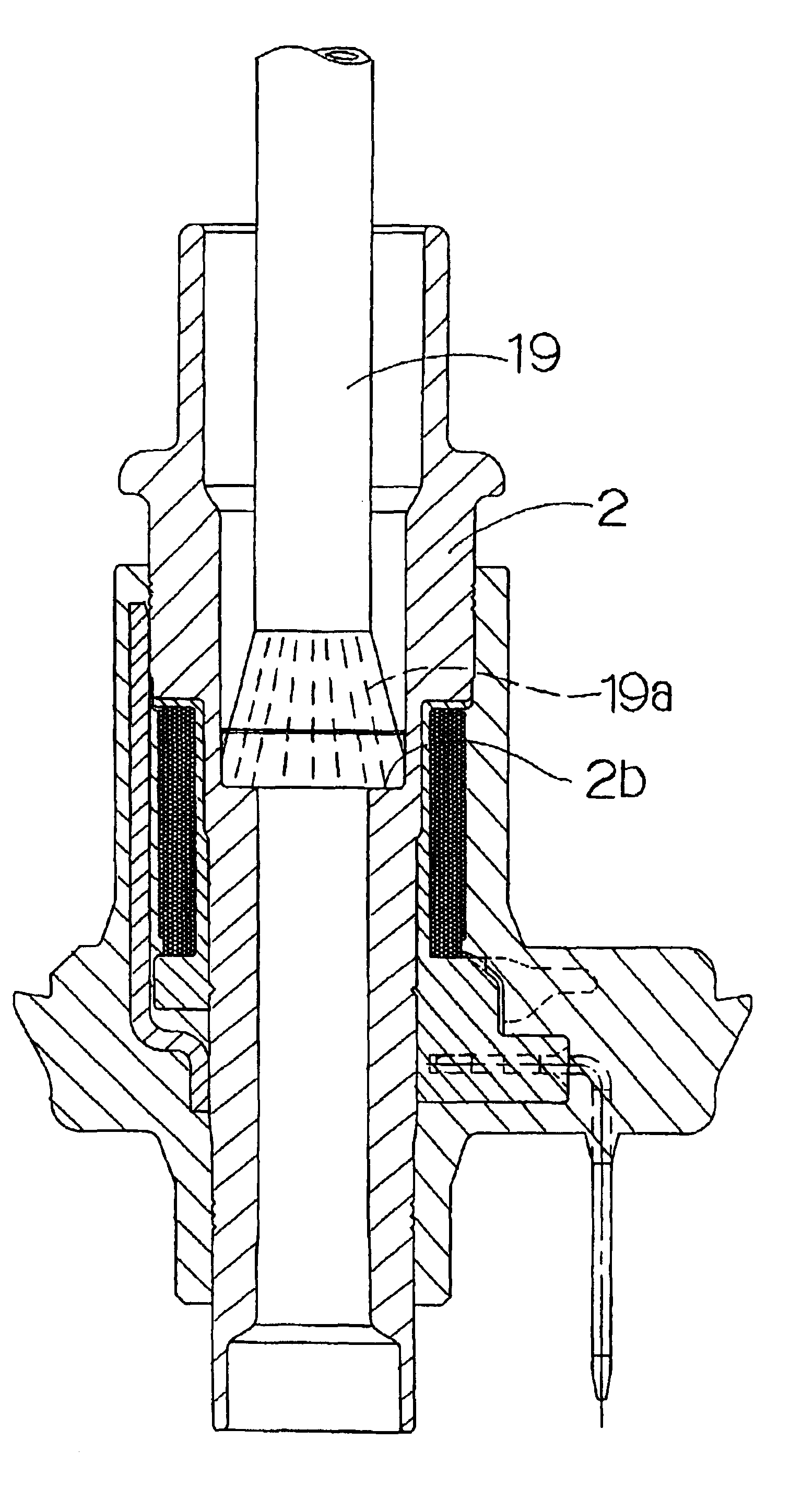
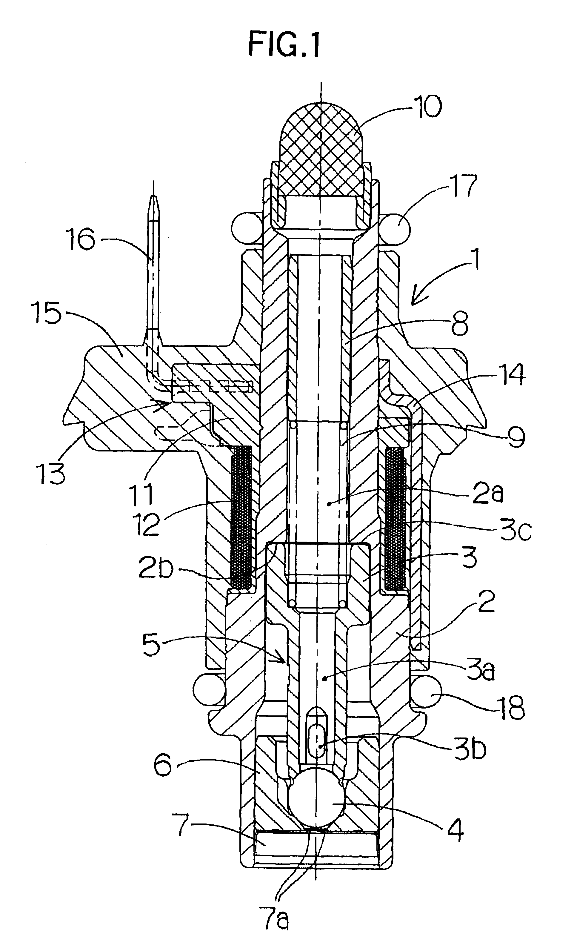
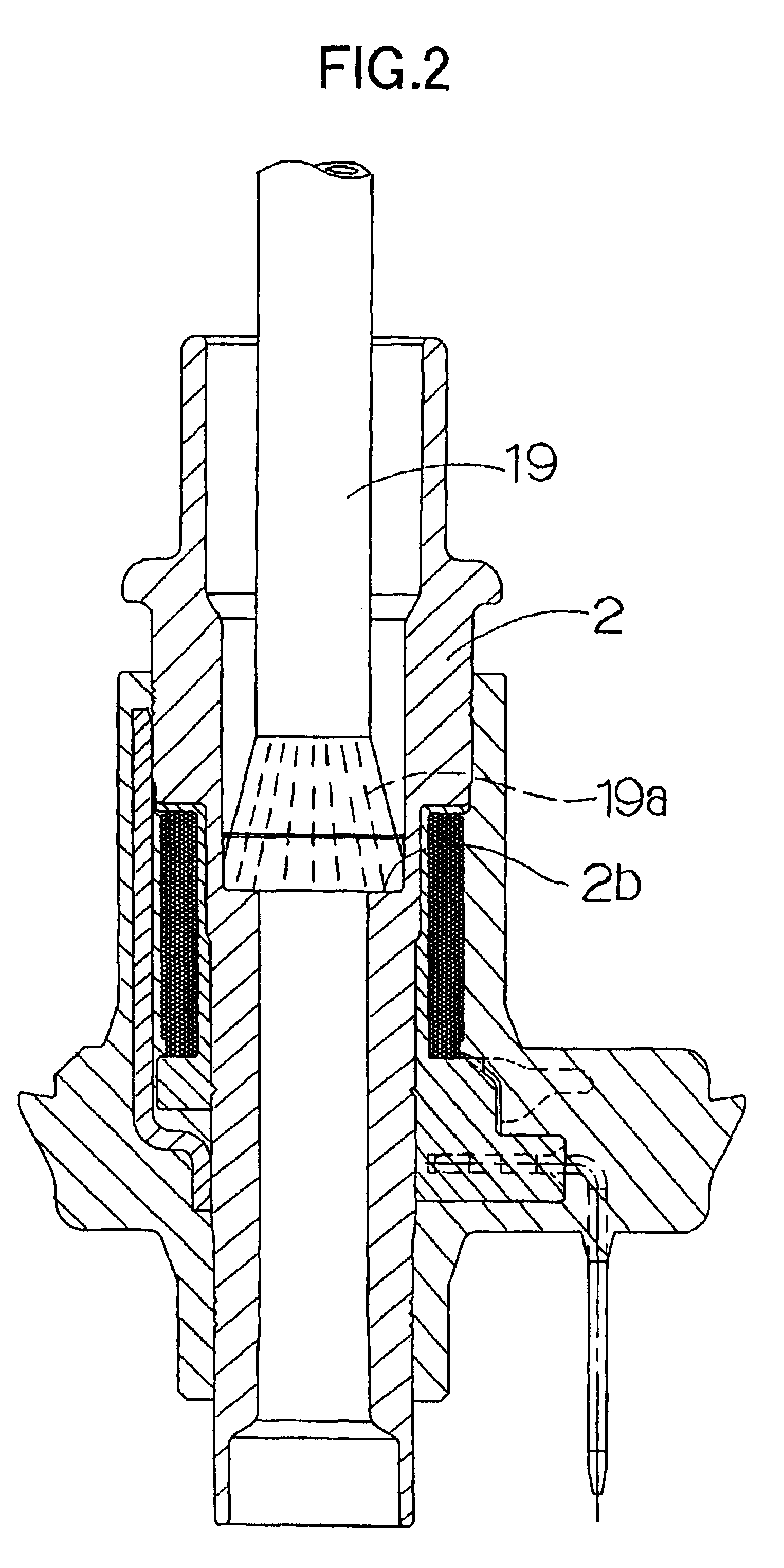
[0015]A preferred embodiment of the present invention will be described below with reference to the accompanying drawings. In FIG. 1, a fuel injection valve 1 includes a stationary core 2. The stationary core 2 has a fuel passage 2a provided in the center thereof. An armature (moving core) 3 is slidably disposed in the fuel passage 2a. A fuel passage 3a is provided in the center of the armature 3 to pass fuel. A ball valve (valving element) 4 is secured to the distal end of the armature 3, for example, by welding to constitute a moving valve 5. A communicating hole 3b is provided in the armature 3 near the ball valve 4 to allow fuel to flow to the outside from the fuel passage 3a. A nozzle 7 is secured to the lower opening of the stationary core 2 by press fitting or welding. The nozzle 7 has a valve seat 6 and an injection port 7a. The moving valve 5 is arranged to move between the valve seat 6 and an abutting surface 2b of the stationary core 2 with an appropriate lift (gap). A cy...
PUM
 Abstract
Description
Claims
Application Information