Print apparatus and printing method for forming a color image by applying different color inks to a printing material using a recording head

a printing method and color image technology, applied in printing mechanisms, printing, spacing mechanisms, etc., can solve the problems of color non-uniformity, low throughput, and lack of fundamental solutions, and achieve the effect of low density portion

Inactive Publication Date: 2005-05-24
CANON KK
View PDF25 Cites 12 Cited by
  • Summary
  • Abstract
  • Description
  • Claims
  • Application Information

AI Technical Summary

Benefits of technology

[0033]When a process color including a secondary color is formed in a pixel using the recording head having such a structure, a plurality of ink droplets are applied from at least one of primary color nozzle, and the nozzles are arranged symmetrically both in the forward scanning and backward scanning directions (main scan direction), by which the differences in the coloring which has conventionally caused by the synchronism with configuration data such as lateral line or the like and by the difference in the shot order at the high density portion can be avoided. Furthermore, the color non-uniformity attributable to the bi-directional print caused by synchronism with half-toning using dither method or the like in the half-tone portion and the low density portion can be suppressed by the provision of control means for providing substantially equal incidence probabilities of orders of shots between the forward path print and the backward path print for the pixels to which a combination of different color dots are allotted.

Problems solved by technology

However, the conventional technique 1) does not provide a fundamental solution, and the throughput is significantly lower when a color image is printed.
3) this is equivalent to use independent two sets of recording heads even if the recording heads for the forward path and the backward path are built in the same substrate, and therefore, a color non-uniformity due to large color difference in the form of bands attributable to the difference of the properties of different heads.
For example, due to the difference in the data ratio of the forward path data to the backward path data, the temperature of the recording head may be different, there arises a difference in the ejection amounts between the recording heads, which would result in the color non-uniformity in the form of bands.
This is a significant problem in a single-path bi-directional printing.
But, the same problem arises in the bi-directional multi-path printing, depending upon the difference in the number of dots to be recorded in the forward path and the number thereof in the backward path, the difference in the number of dots resulting from a thinning mask for supplying the data, or the difference in the number of dots to be print with synchronism with the printing raster.

Method used


Image

  • Print apparatus and printing method for forming a color image by applying different color inks to a printing material using a recording head
  • Print apparatus and printing method for forming a color image by applying different color inks to a printing material using a recording head
  • Print apparatus and printing method for forming a color image by applying different color inks to a printing material using a recording head

Examples


embodiment 1

(Embodiment 1)

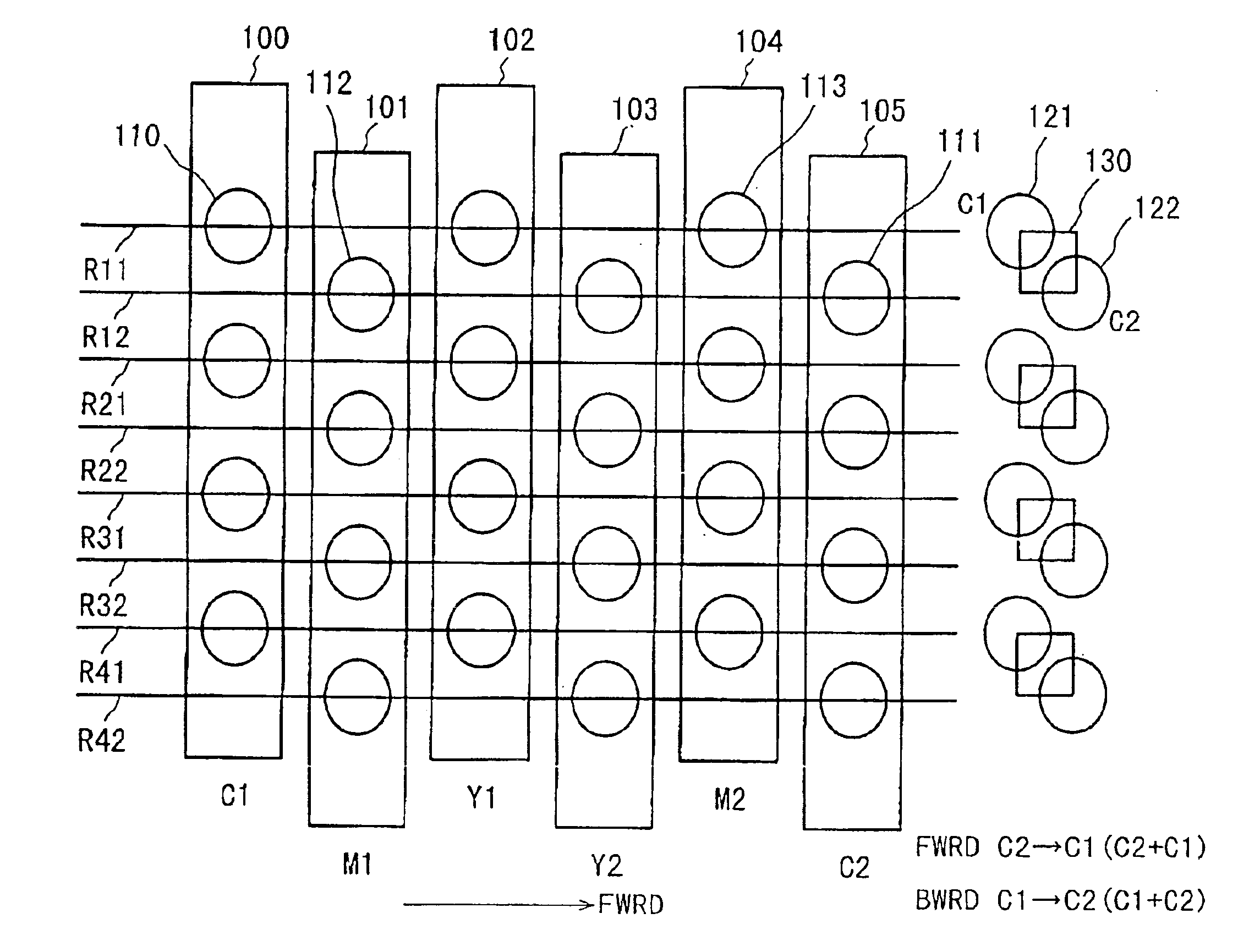
[0081]FIG. 3 is a partial schematic view of a major part of a recording head portion of a head cartridge 1. In this Figure, designated by 100 is a first recording head for ejecting cyan ink (C1). Designated by 101 is a first recording head (M1) for first recording heading magenta ink (M1).

[0082]Designated by 102 is a first recording head for ejecting yellow ink (Y1). Designated by 103 is a second recording head (Y2) for ejecting yellow ink. Designated by104 is a second recording head (M2) for ejecting magenta ink. Designated by 105 is a second recording head (M2) for ejecting cyan ink. Additionally, a recording head for ejecting Bk ink may be used, too.

[0083]The head cartridge 1 is constituted by such said recording heads.

[0084]In head cartridge 1, each of the recording heads includes a plurality of ejection nozzles. For example, the recording head 100C1 includes cyan ejection nozzles 110. The recording head 101M1 includes magenta ejection nozzles 112. The recording he...

embodiment 2

(Embodiment 2)

[0121]FIG. 12 is a schematic view of a major part of a recording head portion of a head cartridge 1 according to another embodiment of the present invention. In this Figure, the constituent-elements are the same as the constituent-elements of the recording head portion shown in FIG. 3. However, the structure of the recording head portion used in this embodiment is different in that pair of the recording heads for the same color for a pixel for each color is deviated relative to the pitch of the nozzles of the recording head by ½ pitch in the sub-scan direction.

[0122]With this structure, the Figure shows the case in which the primary color (cyan) is printed.

[0123]The printing the defective with a pair of two dots at a dot position 121 and a dot position 122 to provide the maximum pixel density for the pixel 130. The dot position 121 and the dot position 122 in the Figure are the positions allotted to the dot elected from the ejection nozzle 110 of the recording head 101...

embodiment 3

(Embodiment 3)

[0139]In the foregoing embodiments, the bi-directional non-uniformity in the single-path bi-directional print is removed using the symmetrical head adapted to the bi-directional print. However, the present invention is effectively applicable also to the case in which the bi-directional print is carried out using a known head in which the recording elements are arranged in the order of colors such as CMYK in the main scan direction.

[0140]This embodiment is characterized in that bi-directional non-uniformity is avoided when the bi-directional print through at least two paths is carried out using a recording head in which the recording elements are simply arranged in the main scan direction, for example, CMYK. In this embodiment, similarly to the foregoing embodiment, the control is effected such that incidence probabilities of pixels at which the orders of shots are different, are substantially the same in the raster one direction, in a low density portion. Furthermore, ...


PUM


Abstract

A printing apparatus for forming a color image by applying different color inks to a printing material while bi-directionally moving the recording head to scan the cording material, the apparatus includes changing device for changing an order of applications of the inks to be applied for printing a secondary color to a secondary color pixel area; forming device for forming the secondary color while making the order of applications of the inks to at least one of a plurality of the secondary color pixel areas arranged along a raster scan direction different from the order of another, by the changing device.

Description

FIELD OF THE INVENTION AND RELATED ART[0001]The present invention relates to a bi-directional printing apparatus and a bi-directional printing method for effecting color print by scanning bi-directionally a printing material with a recording head for applying a plurality of (different) color inks to the printing material, and more particularly to a bi-directional printing apparatus, a bi-directional printing method and a print wherein color non-uniformity attributable to bi-directional color print operation.[0002]In the field of a printing apparatus, particularly an ink jet type printing apparatus, increase of a recording speed for color print is desired. To meet this desire, increase of the length of the recording head, increase of the frequency of actuation of the recording head, bi-directional printing are generally considered. The bi-directional printing is advantageous in that required energy is less concentrated than a unidirectional printing and is scattered in terms of time ...

Claims


Application Information

Patent Timeline
Patent Type & Authority Patents(United States)
IPC IPC(8): B41J19/14B41J19/00B41J2/01B41J5/30B41J2/21
CPCB41J19/147
Inventor OTSUKA, NAOJITAKAHASHI, KIICHIRONISHIKORI, HITOSHIIWASAKI, OSAMUCHIKUMA, TOSHIYUKI
Owner CANON KK
Why Eureka
Try Eureka