
Mold design with improved cooling

Inactive Publication Date: 2005-05-24
GRAHAM PACKAGING CO LP
View PDF6 Cites 13 Cited by
  • Summary
  • Abstract
  • Description
  • Claims
  • Application Information

AI Technical Summary

Benefits of technology

[0004]The invention provides improved cooling of molds by using a split tube cooling loop in portions of the mold that are too small to allow the use of a conventional cooling loop.

Problems solved by technology

The production rate of a blow mold machine if often limited by the amount of time needed to cool a molded container before it can be ejected from its mold.

Method used


Image

  • Mold design with improved cooling
  • Mold design with improved cooling
  • Mold design with improved cooling

Examples


Embodiment Construction

[0013]The invention is explained in the following with the aid of the drawings in which like reference numbers represent like elements.

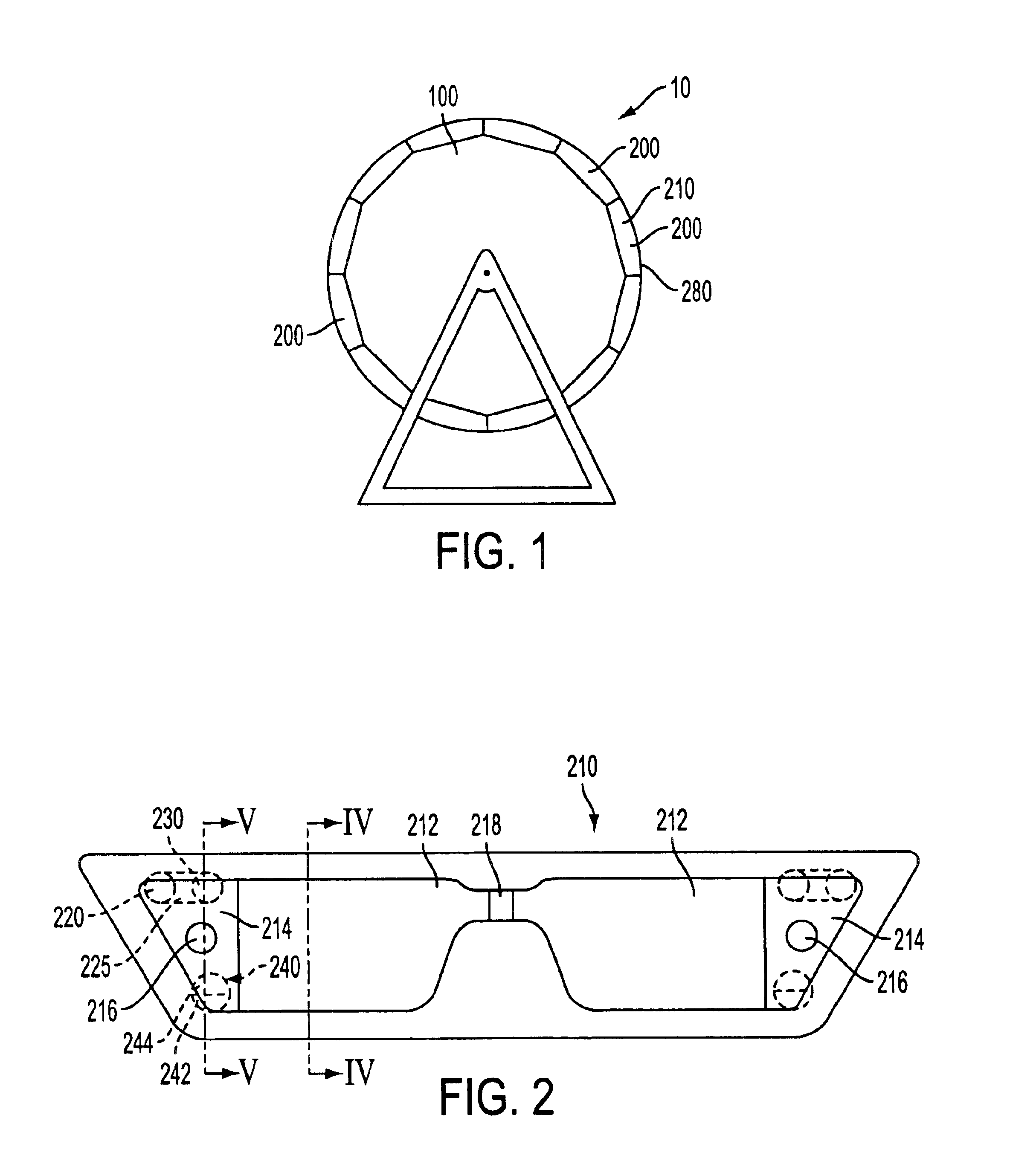
[0014]FIG. 1 shows a schematic side view of a mold machine 10 in accordance with the invention. Mold machine 10 has a mold wheel 100 to which a plurality of molds 200 are attached. In this example, twelve molds 200 are attached to mold wheel 100. Each mold 200 has, in this example, two halves, a first half 210 and a second half 280. In this view, first half 210 is visible and obscures the view of second half 280. In this example, molds 200 are open and closed as mold wheel 100 rotates to produce containers formed by molds 200. Not shown in FIG. 1 are various elements of mold machine 10 such as, for example, extruders to supply a parison, blow air systems, cooling water systems, cam mechanisms, drive systems, and a completed container catching system.

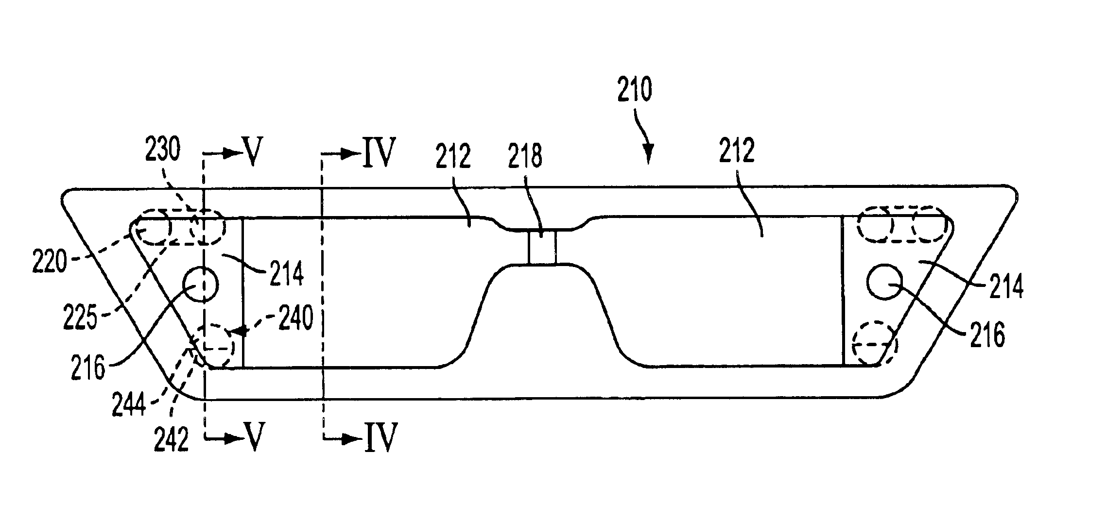
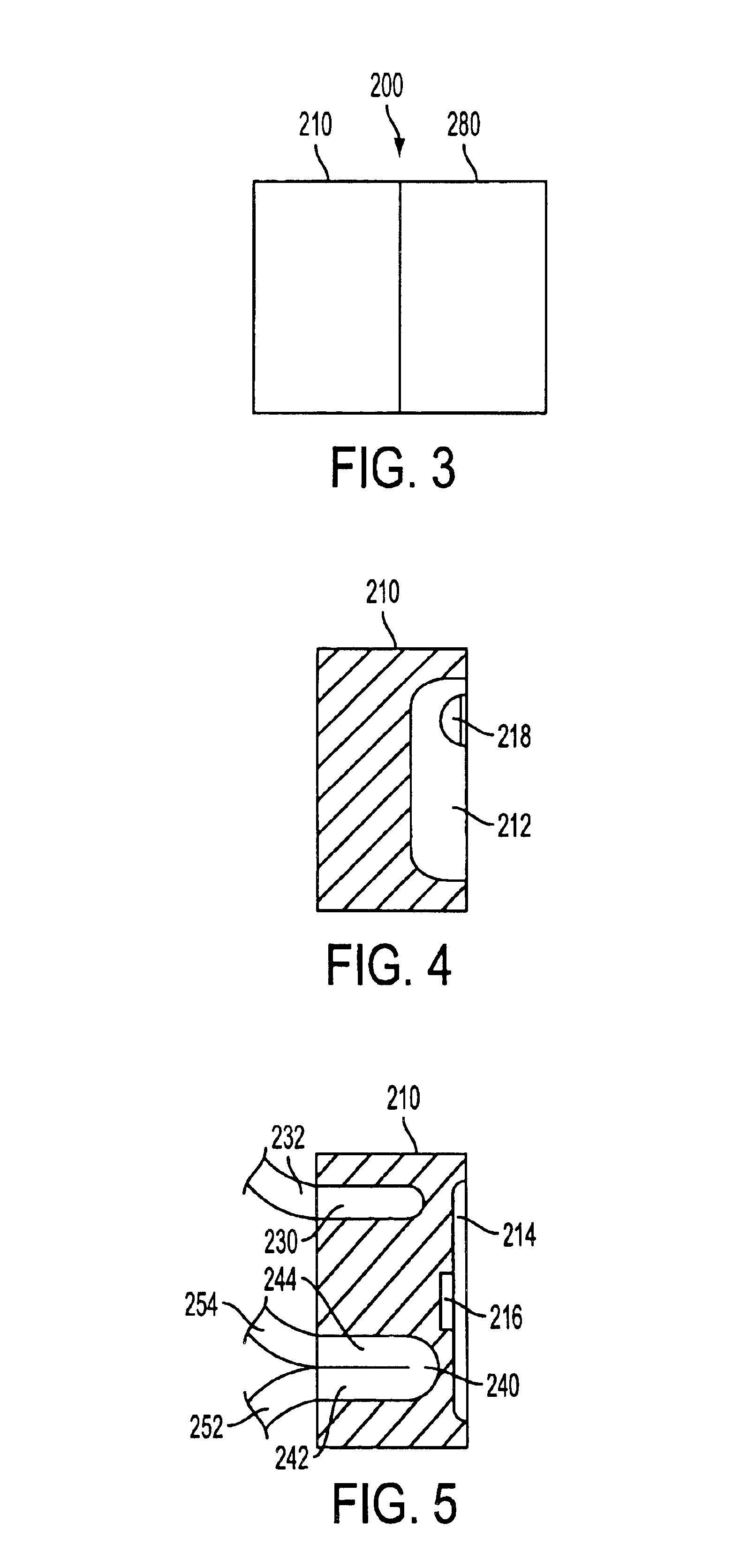
[0015]FIG. 2 shows the side of first mold half 210 that faces second mold half 280 when the mold halve...


PUM

PropertyMeasurementUnit
Diameteraaaaaaaaaa
Moldableaaaaaaaaaa

Abstract

A mold is provided for use with a wheel-type blow mold machine, the mold being one of a plurality of molds for locating in a circular pattern on a wheel of the blow-mold machine and having a longitudinal direction for aligning tangentially with a circumferential direction of the mold wheel and a transverse direction perpendicular to the longitudinal direction. The mold has a first part and a second part. The first part has a first molding portion with a longitudinal end in the longitudinal direction of the mold and a first end portion adjoining the first molding portion at the longitudinal end of the first molding portion and having a free edge opposite the first molding portion, the free edge being non-parallel to the longitudinal direction and the transverse direction. The first part also has an outer cooling circuit located in the first end portion, and an inner cooling circuit located in the first end portion at a different location in the transverse direction than the outer cooling circuit. The inner cooling circuit is a split tube with a first passage of the split tube being for directing a cooling fluid to the first end portion and a second passage of the split tube being for directing the cooling fluid from the first end portion. The second part is separable from the first part and has a second molding portion.

Description

BACKGROUND OF THE INVENTION[0001]The invention relates to a container molding process. More particularly, the invention relates to systems for cooling molds used to mold containers.[0002]It will be understood that to form a polyolefin continuous extrusion blow-molded plastic container, a parison can be heated in an extruder, captured by a mold, and blown in the mold. Specifically, to form the cavity of the container, a parison can be extruded up into the mold and as the mold comes together, a pneumatic blow pin, for example, can pierce the parison and blow the parison up against the walls of the mold. The mold typically contains flash pockets above and below the cavity in the mold to capture the excess of the parison that is forced above and below the cavity. When the parison is blown inside the mold, it is forced into the flash pockets and portions of the parison must adhere together. The excess flash can then be cut away from the container after it is ejected from the mold.[0003]B...

Claims


Application Information

Patent Timeline
IPC IPC(8): B29C49/48B29C49/28B29C49/36B29C49/04
CPCB29C49/36B29C49/4823B29C49/04B29C2049/483B29C2049/4828B29C2049/4825
Inventor CRIDER, MATTKELLY, MIKE
Owner GRAHAM PACKAGING CO LP
Learn More