Stacked multi port connector with light-emitting element

Inactive Publication Date: 2005-05-24
SPEED TECH
View PDF3 Cites 31 Cited by
  • Summary
  • Abstract
  • Description
  • Claims
  • Application Information

AI Technical Summary

Benefits of technology

[0007]Accordingly, in the view of the foregoing, the present inventor makes a detailed study of related art to evaluate and consider, and uses years of accumulated experience in this field, and through several experiments, to create a new stacked multi

Problems solved by technology

However, the conventional stacked multi port network connector is only for allowing a plurality of users to enjoy the service at the same time and that is why the common connector has no display element for identifying the users' status.
Further, because of the structure and the terminal placement of the conventional connector, if the user wants to have a display element on the connector, the transmission end of the display eleme

Method used


Image

  • Stacked multi port connector with light-emitting element
  • Stacked multi port connector with light-emitting element
  • Stacked multi port connector with light-emitting element

Examples


Embodiment Construction

[0018]Reference will be made in detail to the preferred embodiments of the invention, examples of which are illustrated in the accompanying drawings. Wherever possible, the same reference numbers are used in the drawings and the description to refer to the same or like parts.

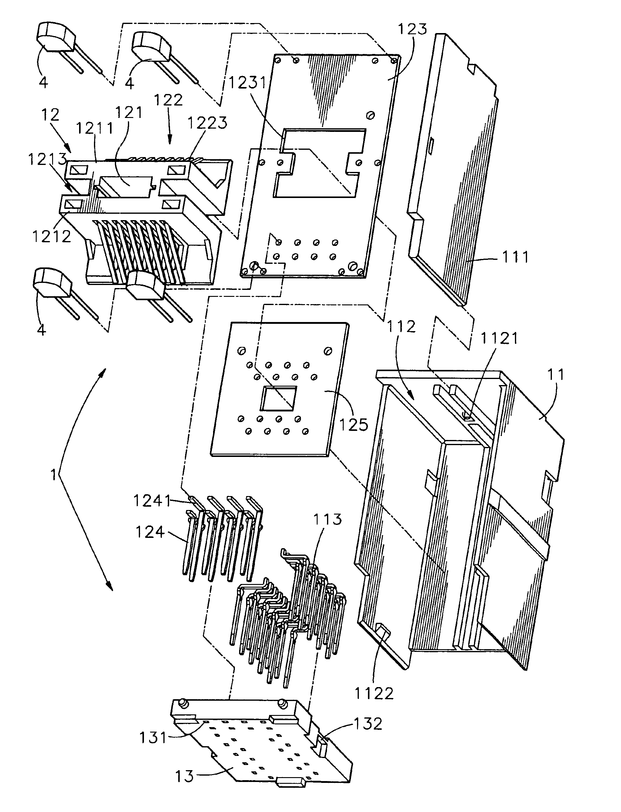
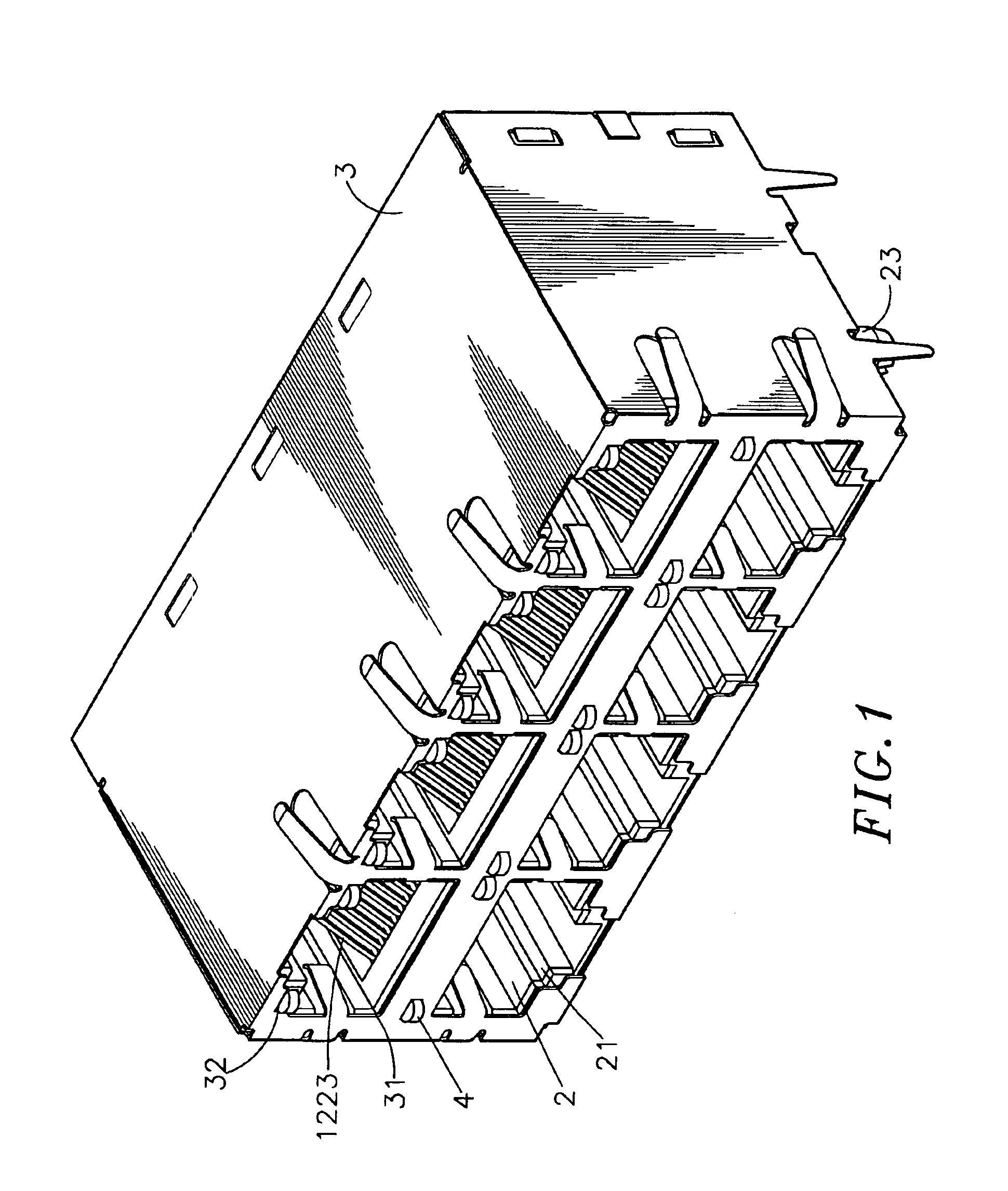
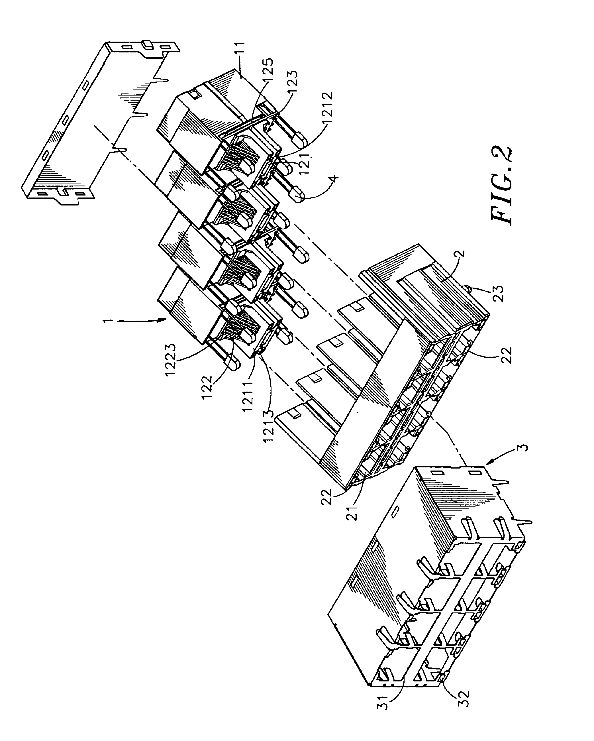
[0019]Referring to FIGS. 1, 2, 3 and 4, an elevational view, an exploded view, an exploded view of a adapting device, back cover and positioning set, and an elevational view of a adapting device, back cover and positioning set, of a stacked multi port connector with light-emitting device according to a preferred embodiment of the present invention are respectively shown. The stacked multi port connector with light-emitting device of the present invention comprises a transmission module 1 and a case 3 covering the transmission module 1. The transmission module 1 comprises a back cover 11, an adapting device 12, a positioning set 13 and a frontal cover 2.

[0020]The back cover 11 comprises a receiving space 112 for ...


PUM


Abstract

A stacked multi port connector with the light-emitting element is described. The stacked multi port connector with the light-emitting element has a transmission module, having an adapting device, a positioning set, a frontal cover and a plurality of light-emitting elements, wherein the adapting device comprises a terminal set having a plurality of signal output terminals penetrating there-through. The positioning set is positioned at a bottom face of the adapting device. The positioning set comprises a plurality of through holes and a plurality of signal input terminals penetrating there-through. The frontal cover comprises a plurality of slots formed on a surface thereon and a plurality of receiving spaces for positioning the light-emitting elements. A plurality of protrusions is formed on two sides of a bottom flange, and wherein the frontal cover covers an outer portion of the adapting device. The signal output terminals of adapting advice are positioned between said protrusions of the frontal cover and signal input terminals of said back cover. A case covers the transmission module.

Description

[0001]This Nonprovisional application claims priority under 35 U.S.C. §119(a) on patent application Ser. No(s). 092205484 filed in TAIWAN on Apr. 8, 2003, the entire contents of which are hereby incorporated by reference.BACKGROUND OF THE INVENTION[0002]1. The Field of the Invention[0003]The present invention is generally related to a stacked multi port connector with light-emitting element, and more particularly to a stacked multi port connector with light-emitting element, wherein a transmission terminal of the adapting device is positioned between the protrusion of the frontal cover and the signal input terminal of the back cover to fit the light-emitting element through the plurality of slots formed on the frontal cover. Accordingly the inclusion of the light-emitting element does not occupy any extra space on the stacked multi port connector, and therefore the size of the stacked multi port connector will not be increased.[0004]2. Description of Related Art[0005]The well-develo...

Claims


Application Information

Patent Timeline
IPC IPC(8): H01R13/66H01R13/717H01R24/00
CPCH01R13/6641H01R13/7175H01R24/64
Inventor CHANG, CHIH-KAI
Owner SPEED TECH
Why Eureka
Try Eureka