Self-cooled electronic equipment enclosure with failure tolerant cooling system and method of operation

Active Publication Date: 2005-05-24
ORACLE INT CORP
View PDF4 Cites 213 Cited by
  • Summary
  • Abstract
  • Description
  • Claims
  • Application Information

AI Technical Summary

Benefits of technology

[0008]In accordance with the principles of the invention, a sealed enclosure with a dedicated cooling system is fitted with movable louvers in the enclosure walls. During normal operation, air pressure developed by the dedicated cooling system keeps the louvers closed and maintains the enclosure sealed to the computer room environment. If the dedicated cooling system fails, the in

Problems solved by technology

Otherwise localized “hot spots” can develop and cause equipment overheating even though the CRAC units can handle the overall cooling load.
In a large data center where equipment is constantly being added, removed and changed, the logistics of maintaining an even cooling load can become difficult.
However, the reduction in electronic component size has resulted in electronic systems currently being built that dissipate 12–20 kilowatts per rack.
Even with proper equipment placement, such systems can cause a hot spot and a cooling over

Method used


Image

  • Self-cooled electronic equipment enclosure with failure tolerant cooling system and method of operation
  • Self-cooled electronic equipment enclosure with failure tolerant cooling system and method of operation
  • Self-cooled electronic equipment enclosure with failure tolerant cooling system and method of operation

Examples


Embodiment Construction

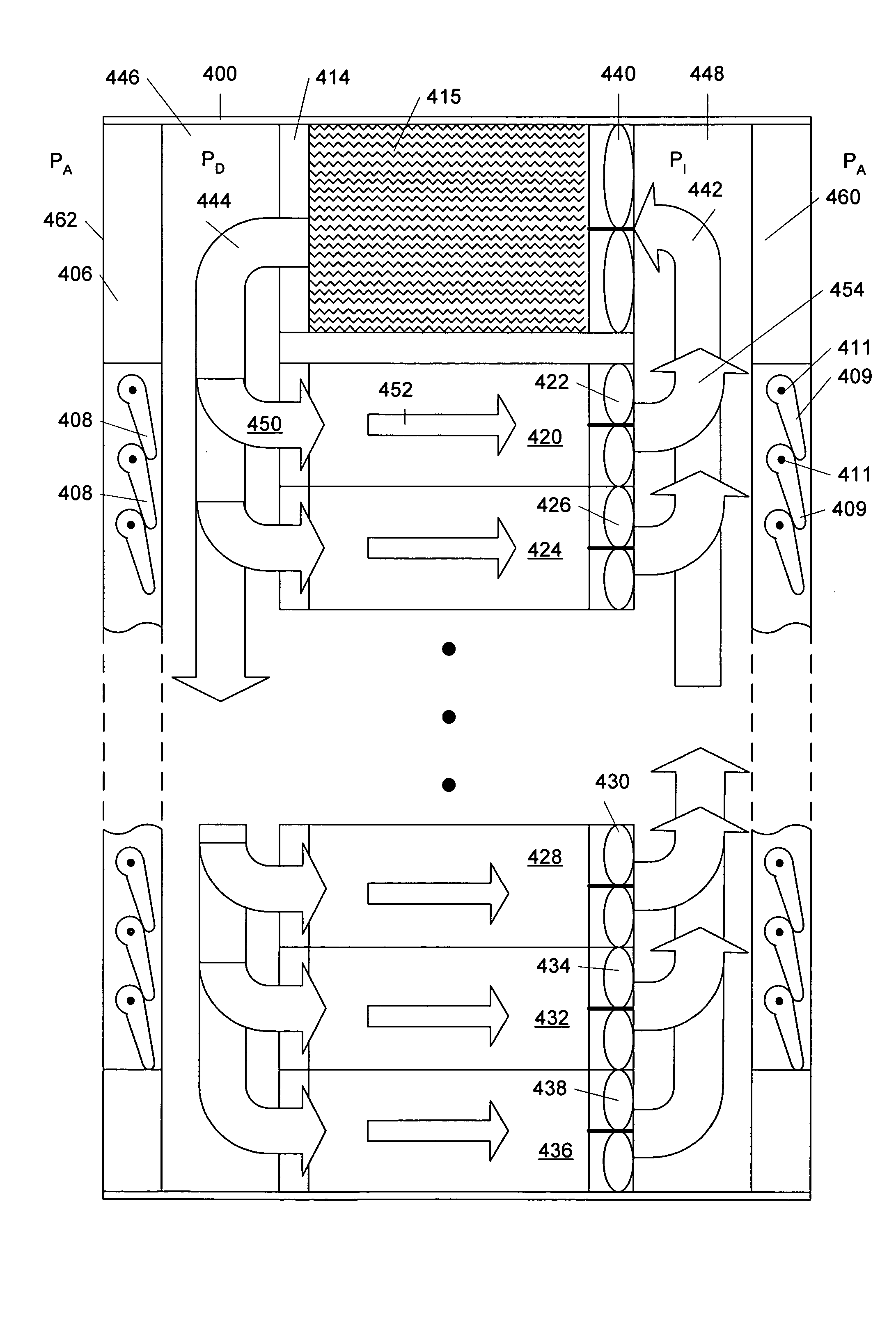
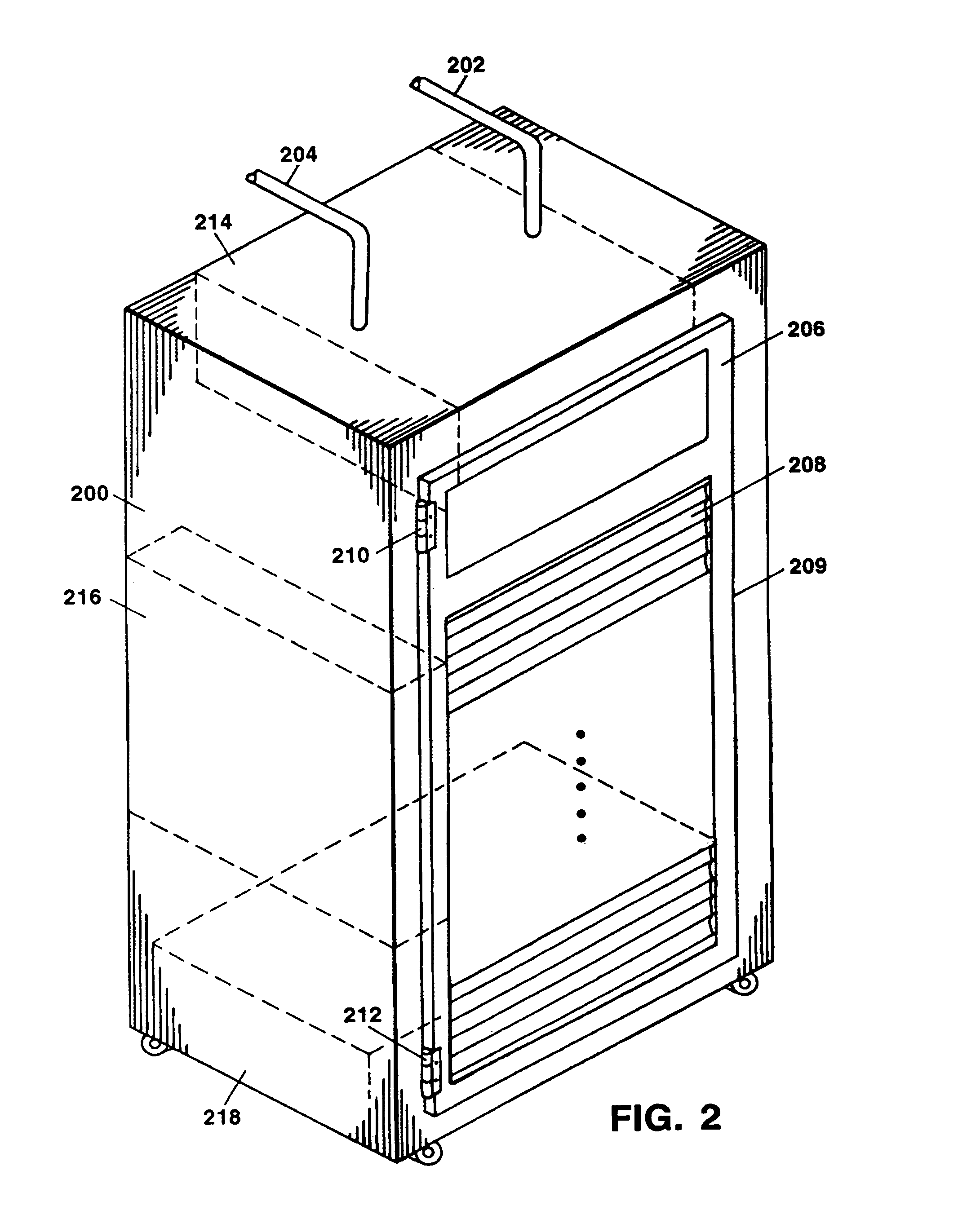
[0021]FIG. 2 is a perspective view of an electronic equipment enclosure 200 including air flow controlled louvers in accordance with the principles of the invention. As shown in FIG. 2, the enclosure 200 may be connected to an external cooling unit that provides a coolant via pipes 202 and 204. Pipes 202 and 204 connect to a heat exchanger.214 located within the enclosure 200. Alternatively, the heat exchanger (or cooling unit) may be located at either the side of enclosure 200 as shown schematically at 216 or on both sides. The heat exchanger (or cooling unit) may also be located at the bottom of enclosure 200 as shown schematically at 218. Alternatively, a self-contained dedicated cooling unit may be used within enclosure 200 in which case pipes 202 and 204 are unnecessary. In all cases the inventive air flow controlled louvers work in the same manner.

[0022]Enclosure 200 is fitted with hinged doors, of which door 206 is shown. Door 206 is attached to enclosure 200 by means of hin...


PUM


Abstract

A sealed electronic equipment enclosure with a dedicated cooling system is fitted with movable louvers in the enclosure walls. During normal operation, air pressure developed by the dedicated cooling system keeps the louvers closed and maintains the enclosure sealed to the computer room environment. If the dedicated cooling system fails, the internal air pressure developed by the cooling system is reduced and air movers in the electronic equipment force the louvers open, thereby allowing the air movers to draw cooled air from the computer room into the enclosure. This cooled air prevents the equipment from overheating at least for a time period long enough to allow the dedicated cooling system to be replaced or repaired.

Description

FIELD OF THE INVENTION[0001]This invention relates to self-cooled electronic equipment enclosures with internal cooling systems and to mechanisms for avoiding equipment shutdown on cooling system failure.BACKGROUND OF THE INVENTION[0002]In many large electronic equipment centers or data centers it is common practice to mount electronic equipment in enclosures called “racks.” In order to cool the equipment, the racks have open fronts and backs and are placed in an air-conditioned computer room. The interior of a typical computer room 100 is illustrated in FIG. 1. In such a room, a raised floor 103 is constructed over the actual floor 102. The raised floor is conventionally constructed of a grid framework 104 that supports modular floor panels 106. The racks of equipment, of which racks 116, 118, 120, 122 and 124 are shown, are placed on the raised floor 103. Typically, channels 130 and 132 run across the tops of the racks to allow the electronic equipment to be interconnected by cabl...

Claims


Application Information

Patent Timeline
IPC IPC(8): H05K7/20
CPCH05K7/20618H05K7/20781H05K7/20754H05K7/20745
Inventor NOVOTNY, SHLOMO D.
Owner ORACLE INT CORP
Why Eureka
Try Eureka