
Polymer insulator apparatus and method of mounting same

a technology of polymer insulators and insulators, which is applied in the direction of electrical devices, applications, pasturing equipment, etc., can solve the problems of insufficient rigidity of polymer post insulators, brittle insulators made of porcelain, and insufficient rigidity of insulators, so as to improve the strength in the direction of cantilever load and in particular the strength in the direction of compression load, and improve the strength in the desired direction.

Inactive Publication Date: 2005-05-24
NGK INSULATORS LTD
View PDF24 Cites 7 Cited by
  • Summary
  • Abstract
  • Description
  • Claims
  • Application Information

AI Technical Summary

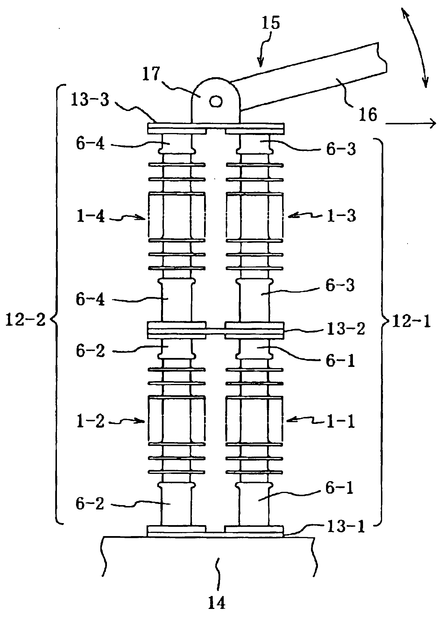
Benefits of technology

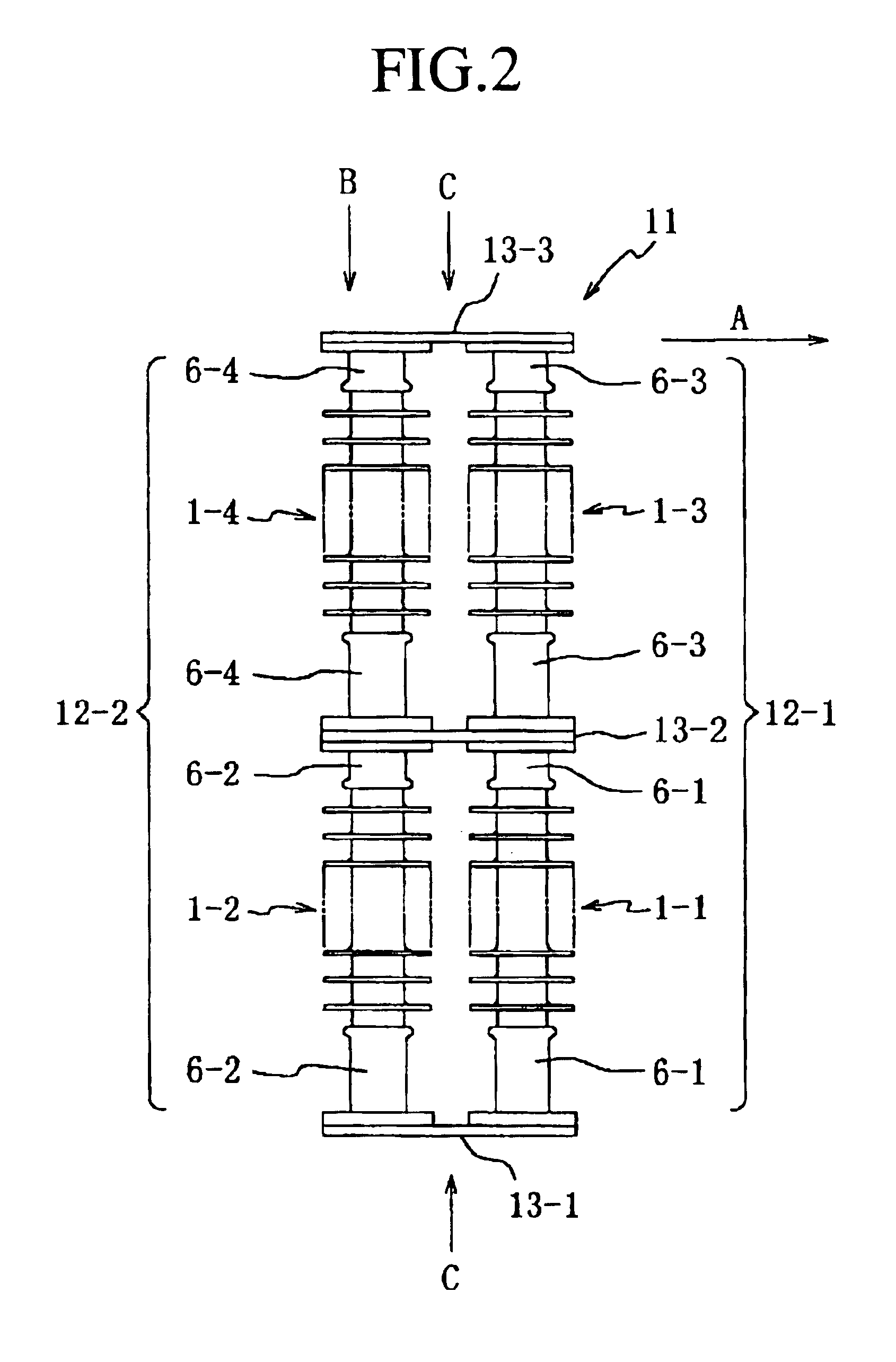
[0008]A polymer insulator apparatus according to the present invention is such that polymer post insulator columns, in which plural polymer post insulators are stacked, are arranged in parallel, and the polymer post insulator columns arranged in parallel are connected with each other via a connecting plate at each connection site of the polymer insulator constituting the polymer insulator columns as well as at the top and bottom of the polymer post insulator columns, whereby the cantilever strength in a direction of arranging the polymer post insulator columns in parallel is increased, and also the compression strength in a direction of stacking the polymer post insulators is increased.
[0010]In the present invention, polymer post insulator columns, in which plural polymer post insulators are stacked, are arranged in parallel, and the polymer post insulator columns arranged in parallel are connected with each other via a connecting plate at each connection site of the polymer insulator consisting the polymer insulator columns as well as at the top and bottom of the polymer post insulator columns. Therefore, in mounting the above-described polymer insulator apparatus vertically onto a base, the polymer post insulator apparatus can be mounted so that the direction of arranging the polymer post insulator columns in parallel will be a direction of cantilever load and the direction of stacking the polymer post insulators will be a direction of compression load. For this reason, the strength in the direction of cantilever load and the strength in the direction of compression load in particular can be improved.
[0011]Of course, the strength in a desired direction can be improved by setting the direction of parallel arrangement of the polymer post insulator columns to be an arbitrary direction. Also, the strength in a direction other that the direction of improved strength can be improved as compared with the strength in a case of a single polymer post insulator, though the improvement is not great as in the direction of improved strength. Further, the polymer insulator apparatus according to the present invention is constructed in such a manner that polymer post insulator columns, in which plural polymer post insulators are stacked, are arranged in parallel, and the polymer post insulator columns arranged in parallel are connected with each other via a connecting plate at each connection site of the polymer insulator constituting the polymer insulator columns as well as at the top and bottom of the polymer post insulator columns. Therefore, a long polymer insulator apparatus can be obtained easily while maintaining the diameter of the FRP core of each polymer post insulator constituting the polymer insulator apparatus to be of the same degree as in the prior art.
[0012]Furthermore, in a preferable mode, the polymer post insulator columns are arranged in parallel in the direction of the cantilever load generated by opening and closing of a switching device. Disposing the polymer post insulator columns in such a manner is preferable because of the following reason. When a switching device of a substation is constructed with the polymer insulator apparatus of the present invention, the cantilever load imposed upon the top by an operation of the opening / closing part is applied in the direction of great improvement of the strength of the polymer insulator apparatus. Therefore, a sufficient position precision can be maintained against a larger cantilever load, and also the polymer insulator apparatus can exhibit a sufficient strength against the compression load imposed upon the polymer insulator apparatus by placing the opening / closing part thereon.

Problems solved by technology

However, insulators made of porcelain are brittle, and are not durable against a dynamic stress such as generated in a large earthquake or the like.
For this reason, in application of polymer post insulators for substations, insufficient rigidity of the polymer post insulators is a problem particularly for high voltage that requires a long insulation distance.

Method used


Image

  • Polymer insulator apparatus and method of mounting same
  • Polymer insulator apparatus and method of mounting same
  • Polymer insulator apparatus and method of mounting same

Examples


Embodiment Construction

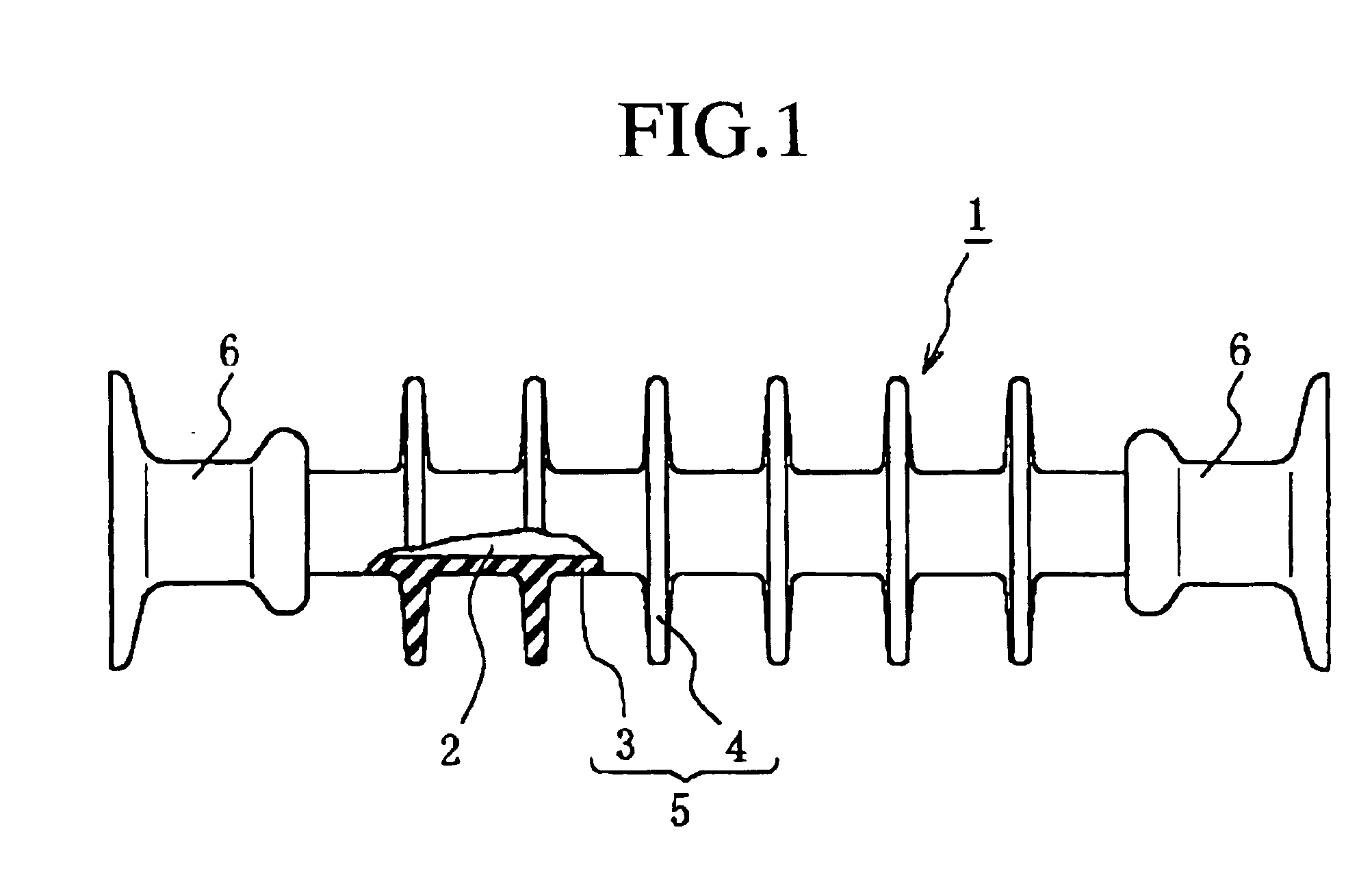
[0023]FIG. 1 is a view showing one construction example of a polymer post insulator constituting a polymer insulator apparatus according to the present invention. In the example shown in FIG. 1, a polymer post insulator 1 is constituted with a core member 2, an outer cover 5 constructed by a sheath 3 and sheds 4 disposed around core member 2, and holding metal fitting pieces 6 disposed at two ends of core member 2. Further, core member 2 is made of a solid FRP, and outer cover 5 constructed by sheath3 and sheds 4 is made of, for example, silicone rubber. Also, an end of holding metal fitting piece 6 has a flange shape, and is constituted to be capable of being fixed onto a planar plate member or the like with screws. The construction of this polymer post insulator is the same as in the prior art.

[0024]FIG. 2 is a view showing one example of a polymer insulator apparatus according to the present invention. In the example shown in FIG. 2, a polymer insulator apparatus 11 according to ...


PUM


Abstract

The cantilever and compression strength of a polymer post insulator decreases according to lengthening of lever length of the polymer post insulator. By combining polymer post insulators to construct a structure having an increased strength in an arbitrary direction, a polymer insulator apparatus and a method for mounting the same can provide a sufficient strength and rigidity even as a long insulator for high voltage that requires a long insulation distance. Polymer post insulator columns 12-1, 12-2, in which plural polymer post insulators 1-1 to 1-4 are stacked, are arranged in parallel. The polymer post insulator columns 12-1, 12-2 arranged in parallel are connected with each other via connecting plates 13-1 to 13-3 at each connection site of the polymer post insulators 1-1 to 1-4 constituting the polymer post insulator columns 12-1, 12-2 as well as at the top and bottom of the polymer post insulator columns 12-1, 12-2. Thus, the cantilever strength in a direction of arranging the polymer post insulator columns 12-1, 12-2 in parallel is increased, and also the compression strength in a direction of stacking the polymer post insulators 1-1 to 1-4 is increased.

Description

REFERENCE TO RELATED APPLICATION[0001]This application claims priority from Japanese Application 2002-380961 filed Dec. 27, 2002, the entireties of which is incorporated herein by reference.BACKGROUND OF THE INVENTION[0002]1. Field of the Invention[0003]The present invention relates to a post insulator that receives a large compression load by supporting an electric conductor, a switching device, or the like, for example, in a substation. In particular, the present invention relates to an insulator apparatus constituted with polymer post insulators and to a method of mounting the same.[0004]2. Description of the Background Art[0005]Hitherto, since post insulators used in a substation not only support an electric conductor but also are structural members constituting a transformer apparatus, a high rigidity is required and also, in a post insulator that supports an opening / closing part of a switching device, a strict position control is required in order to ensure an accurateness in ...

Claims


Application Information

Patent Timeline
IPC IPC(8): H01B17/14H01B17/18H01B17/00
CPCH01B17/18
Inventor FUJII, SHUJI
Owner NGK INSULATORS LTD
Learn More