
Molded/integrated touch switch/control panel assembly and method for making same

Inactive Publication Date: 2005-05-24
TOUCHSENSOR TECH
View PDF6 Cites 171 Cited by
  • Summary
  • Abstract
  • Description
  • Claims
  • Application Information

AI Technical Summary

Benefits of technology

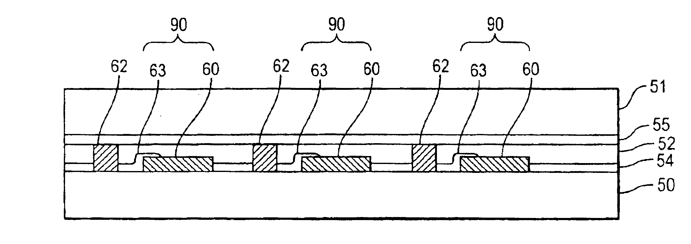
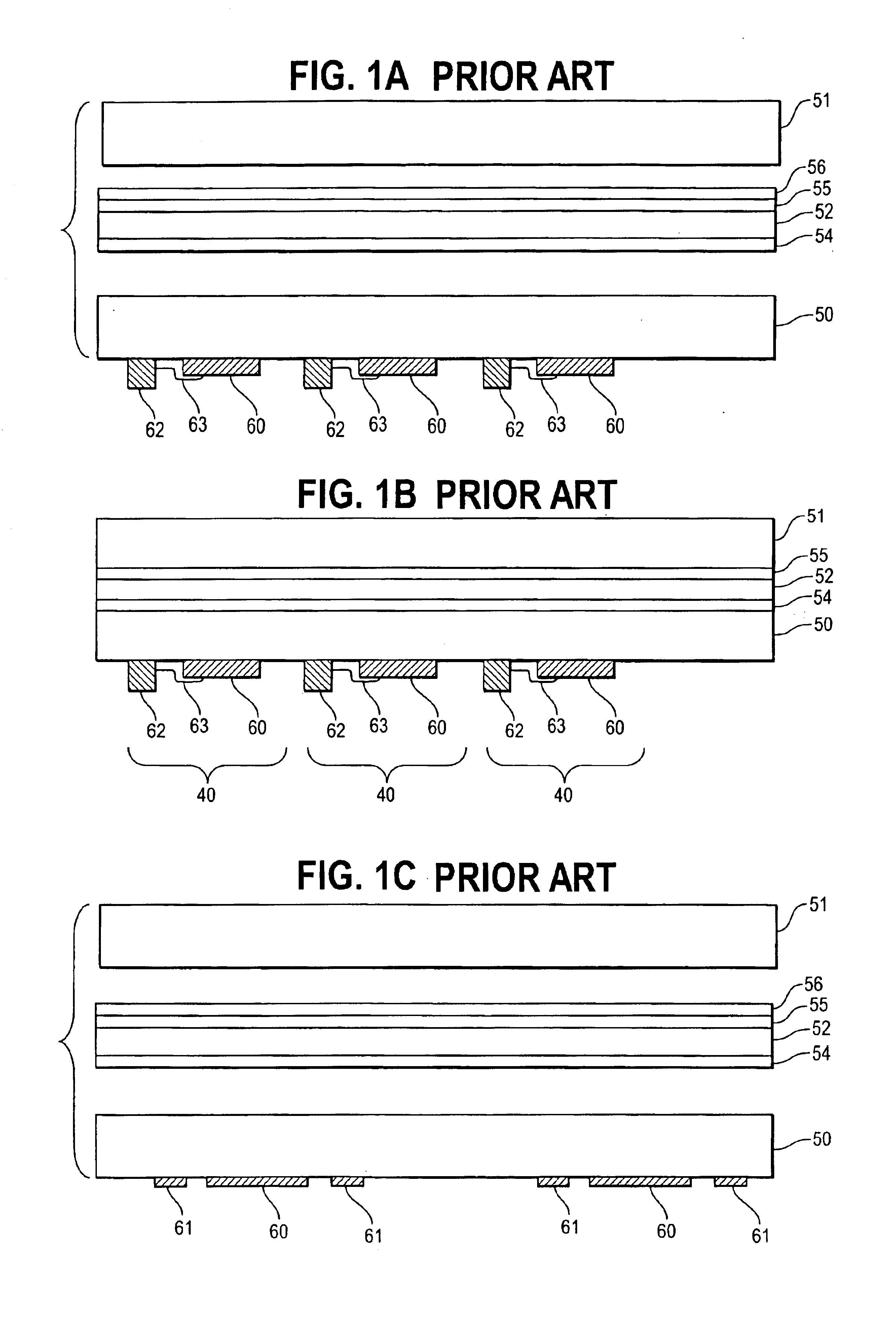
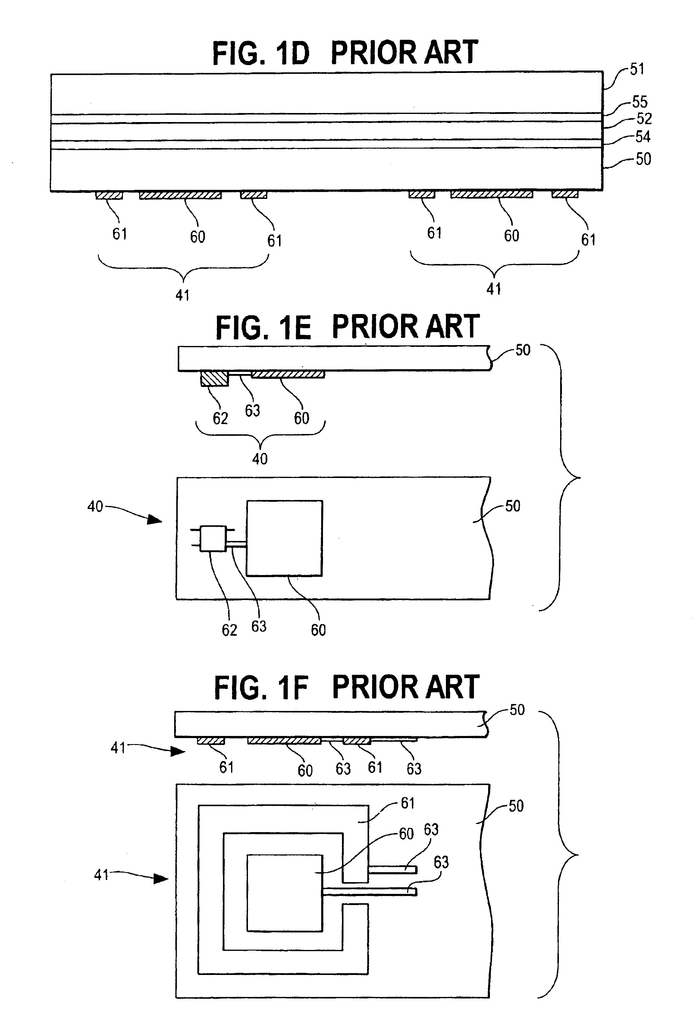
[0009]The present invention overcomes shortcomings of the prior art by integrating touch switch carriers with other substrates which then serve as control panels having touch surfaces corresponding to the underlying touch switches. For example, the present invention integrates touch switches and their carriers with touch surface substrates using molding processes such as thermoforming or injection molding and the like. Mechanical anchors and adhesives can be used in connection with such molding techniques to further ensure positive engagement of individual components into an integrated touch switch / control panel assembly.
[0010]Integrated touch switch / control panel assemblies according to the present invention can include depressions and ridges that provide tactile feedback to a user and can include bezels and housings that frame the user interface portion of the molded substrates. Also, integrated touch switch / control panel assemblies according to the present invention can be embodied as components of larger and more complex assemblies. For example, the present invention could be used to integrate touch switches for operating an automobile's electric windows into the automobile's door panels or center console. The integrated touch switch / control panel assemblies of the present invention can simplify the manufacturing process, reduce manufacturing costs, optimize touch switch performance, allow more flexibility in touch switch design and, thereby and otherwise, increase the number and type of applications for which touch switches are suitable.

Problems solved by technology

While the foregoing conventional assembly techniques generally are effective, they sometimes provide less than optimal integration of the touch switch carrier to the touch surface substrate, thus potentially adversely affecting the operation of the touch switch.
For instance, stud and bracket attachment methods sometimes yield inconsistent spacing between touch pads and the corresponding touch surfaces on the touch surface substrate because of mechanical irregularities in the attachment components, the touch switch carrier, and / or the touch surface substrate.
Also, stud and bracket assemblies can come apart, particularly in vibratory or other harsh environments.
Simple adhesive attachment methods can yield inconsistent spacing between touch switches and corresponding touch surfaces in cases where adhesive is unevenly applied between the touch switch carrier and the touch surface substrate.
Also, bubbles and other inconsistencies in the composition of the adhesive itself can adversely affect the performance of the touch switch.
Further, the foregoing conventional techniques impose limitations on the design of the final touch switch / touch surface interface.
Attaching a touch switch to a non-flat substrate using conventional attachment techniques can pose problems related to the complexity of the attachment process and the surety of the attachment itself.

Method used


Image

  • Molded/integrated touch switch/control panel assembly and method for making same
  • Molded/integrated touch switch/control panel assembly and method for making same
  • Molded/integrated touch switch/control panel assembly and method for making same

Examples


Embodiment Construction

[0035]While the drawings generally depict capacitive and electric field touch switches for the purpose of illustration, the principles of the present invention can be seen by those skilled in the art as appropriate for any manner of touch switch device, including, but not limited to, capacitive touch switches, infrared touch switches, electric field touch switches, acoustic touch switches and electromagnetic touch switches. Specific examples include the touch switches described in U.S. Pat. Nos. 5,594,222, 5,856,646, 6,310,611 and 6,320,282, each naming David W. Caldwell as inventor. The disclosures of the foregoing U.S. patents are hereby incorporated herein by reference. The disclosures of U.S. patent applications Ser. No. 10 / 271,933, entitled Intelligent Shelving System, No. 10 / 272,377, entitled Touch Switch with Integrated Control Circuit, No. 10 / 272,047, entitled Touch Sensor with Integrated Decoration, and No. 10 / 271,438, entitled Integrated Touch Sensor and Light Apparatus, a...


PUM

PropertyMeasurementUnit
Flexibilityaaaaaaaaaa
Moldableaaaaaaaaaa
Mechanical propertiesaaaaaaaaaa

Abstract

Touch switches are integrated with thermoformable, injection molded, and other substrates to yield integrated touch switch / control panel assemblies. The ensuant assemblies can include ridges, depressions, anchors, overlaps, rivets and bezels or other housings. They can have any combination of flat and curved surfaces. Further, such assemblies can be incorporated into components of other assemblies, such as automobiles.

Description

CROSS-REFERENCE TO RELATED APPLICATIONS[0001]This application claims priority from U.S. Provisional Patent Applications No. 60 / 334,040, filed on Nov. 20, 2001; and Nos. 60 / 341,350, 60 / 341,550 and 60 / 341,551, filed on Dec. 18, 2001. The disclosures of these applications are hereby incorporated herein by reference.BACKGROUND OF THE INVENTION[0002]1. The Technical Field[0003]The present invention relates to touch switches. More particularly, it relates to the integration of touch switches into control panels and other substrates using molding techniques such as thermoforming, injection molding, and the like.[0004]2. The Prior Art[0005]Touch switches have many advantages over and have long been used as replacements for mechanical switches. Known touch switches typically include a touch pad and an associated control circuit. Such a touch pad typically consists of one or more electrodes and, in some cases, other electronic components, mounted on a rigid or flexible carrier. The associated...

Claims


Application Information

Patent Timeline
IPC IPC(8): A47F5/00A47F3/00A47F3/06A47B57/00A47B96/02G09F3/08G09F9/30G09F3/20H03K17/94H03K17/96
CPCA47B57/00A47B96/025A47F3/06A47F5/0043G09F3/204G09F9/30H03K17/96H03K17/962F25D2325/022Y10T29/49105F25D2331/803
Inventor CALDWELL, DAVID W.BIRD, KEVIN C.SCHAEFER, WILLIAM D.
Owner TOUCHSENSOR TECH
Learn More