

Instrument and method for measuring ejection velocity of liquid
a technology of ejection velocity and measuring device, which is applied in the direction of instruments, using reradiation, and investigating moving fluids/granular solids, etc., can solve the problems of not yet being embodied a liquid jetting apparatus, not yet being able to measure the velocity of liquid droplets ejected from the nozzle orifice with sufficient accuracy and durability, etc., to achieve the elimination of the influence of so-called satellite droplets, accurate measurement, and short period of time
- Summary
- Abstract
- Description
- Claims
- Application Information
AI Technical Summary
Benefits of technology
Problems solved by technology
Method used
Image

Examples
first embodiment
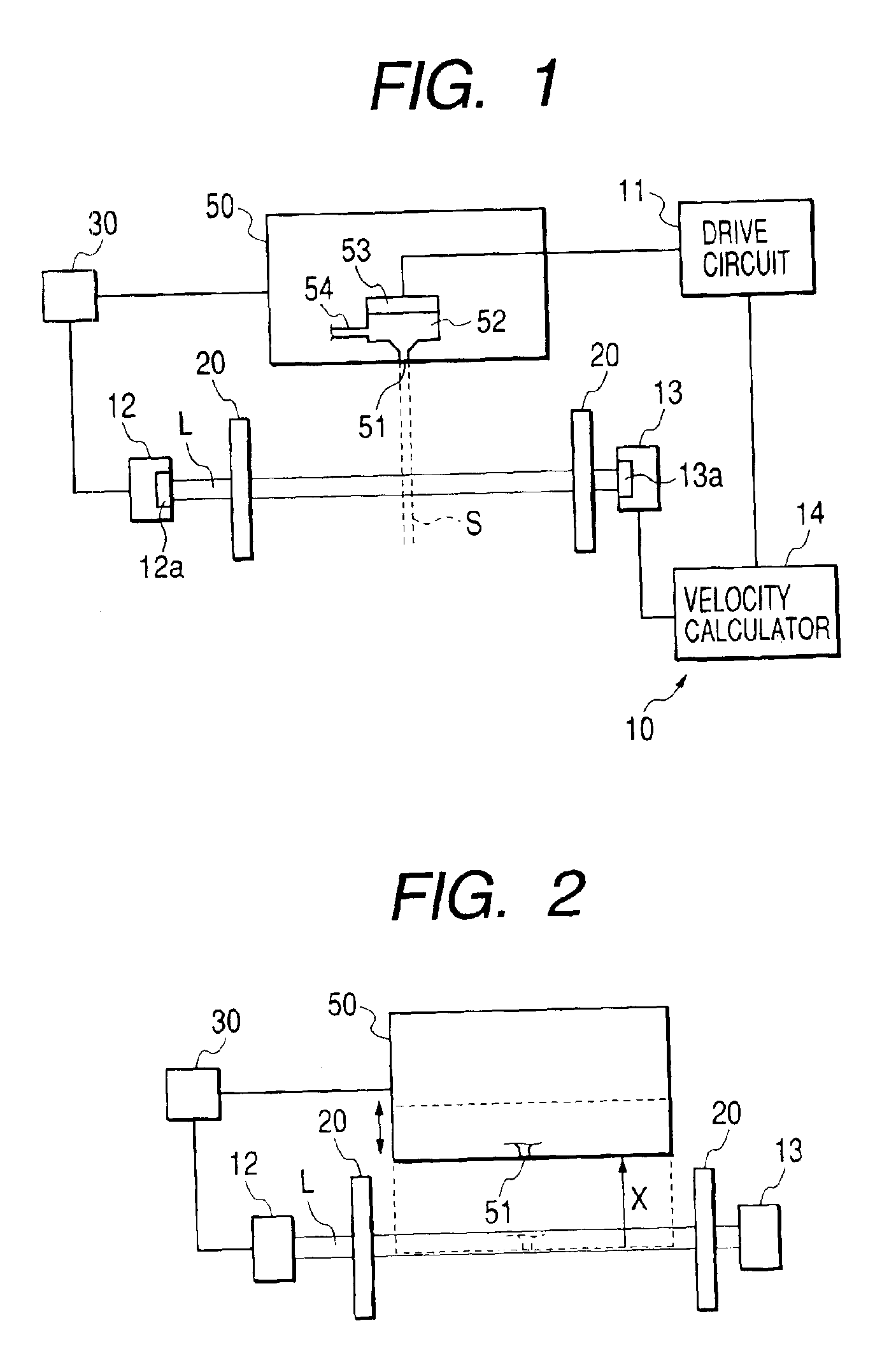
[0122]As shown in FIG. 1, an ejection velocity measuring device 10 according to the invention is provided for a head member 50.
[0123]The head member 50 comprises nozzle orifice 51; a pressure generating chamber 52 which is in communication with the nozzle orifice 51 and stores liquid therein; a liquid supply channel 54 for supplying liquid to the pressure generating chamber 52; and a pressure generator 53 which ejects a liquid droplet from the nozzle orifice 51 by changing the pressure of the liquid stored in the pressure generating chamber 52. Here, the pressure generator 53 is a piezoelectric vibrator. The pressure generator 53 may be constituted of a heater or the like. For example, a liquid droplet is an ink droplet including coloring material for drawing an image on recording paper.
[0124]The ejection velocity measuring device 10 comprises a drive circuit 11 for driving the pressure generator 53; a light emitter 12 for emitting light along a trajectory L (hereinafter called a “o...
second embodiment
[0147]For this reason, by reference to FIG. 5, there will now be described the invention particularly taking into consideration of such a case.
[0148]A position adjuster 30 of the embodiment shown in FIG. 5 is arranged so as to enable at least two ways of setting of a distance between the position of the nozzle orifice 51 of the head member 50 and the trajectory L of light originating from the light emitter 12. On the basis of the state of light received by the light receiver 13 according to the two ways of setting, the velocity calculator derives the velocity of a liquid droplet ejected from the nozzle orifice 51.
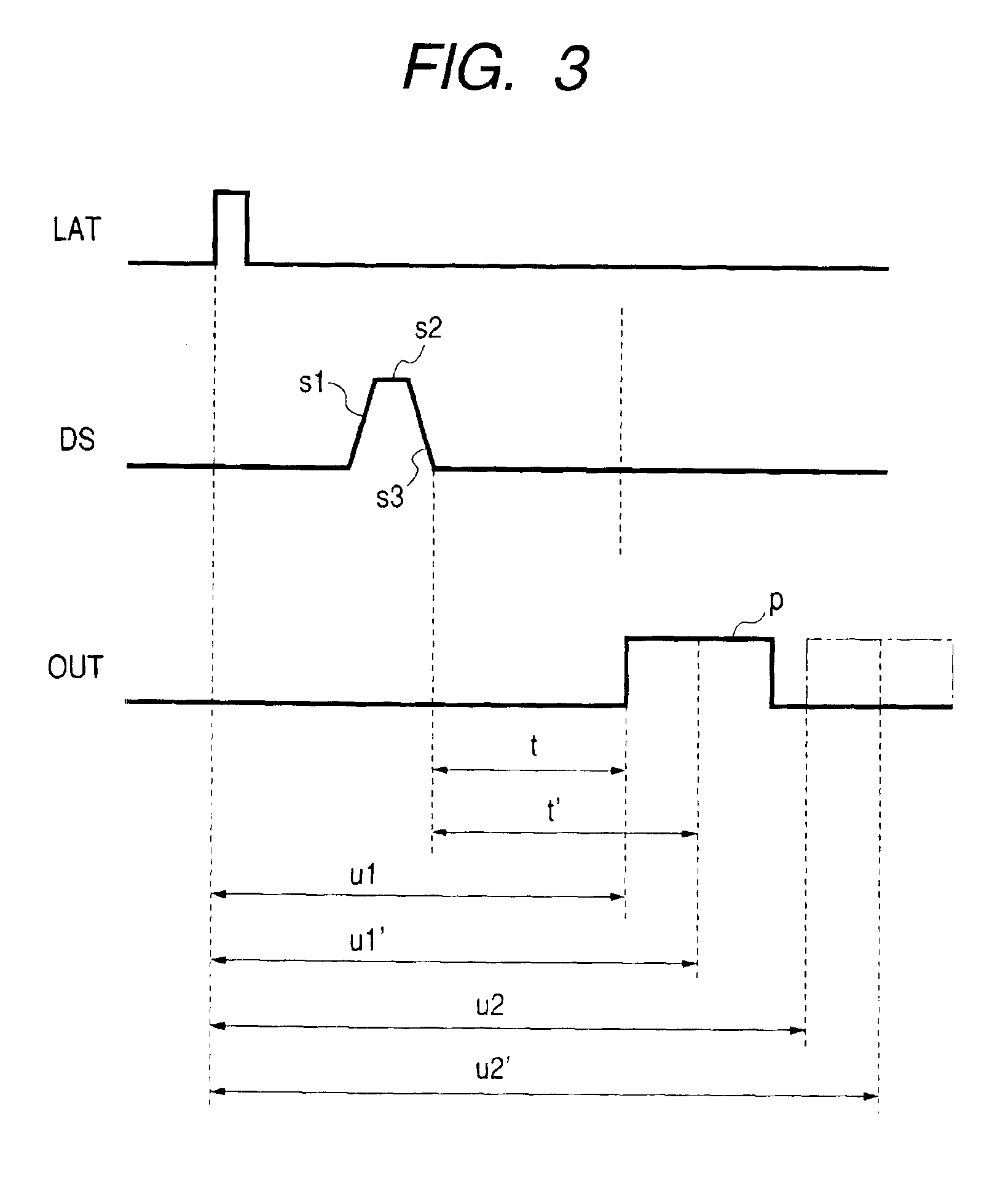
[0149]As shown in FIG. 5, the distance between the position of the nozzle orifice 51 and the trajectory L of the light originating from the light emitter 12 is assumed to be set to x1 and x2. In connection with the setting of distance x1, the velocity calculator 14 calculates a time period u1 from a timing at which the latch signal LAT is supplied to a timing at which the p...
third embodiment
[0154]In place of the distance between the position of the nozzle orifice 51 and the trajectory L of the light originating from the light emitter 12 being set in two ways, two trajectories of light may be prepared beforehand. Such a configuration will now be shown in FIG. 6 as a
[0155]The ejection velocity measuring device 10 of the embodiment further comprises: a second light emitter 12′ for emitting light on a second trajectory L′ which crosses the liquid droplet passage space S; and a second light receiver 13′ for receiving light of second trajectory L′ crossing the liquid droplet passage space S.
[0156]More specifically, the second light emitter 12′ also has a semiconductor laser 12a′, and the second light receiver 13′ also has a photodiode 13a′. The light emitted from the semiconductor laser 12a′ is received by the photodiode 13a′ while crossing the liquid droplet passage space S.
[0157]The layout of a second trajectory L′ of light (hereinafter called a “second light trajectory”),...
PUM
 Abstract
Description
Claims
Application Information