Axial flux motor with active flux shaping

Inactive Publication Date: 2005-05-24
CHIARENZA KEVIN J
View PDF9 Cites 29 Cited by
  • Summary
  • Abstract
  • Description
  • Claims
  • Application Information

AI Technical Summary

Benefits of technology

[0013]The '318 application discloses an axial flux motor utilizing one stator coil per two rotor disks and two assemblies of the aforementioned rotor disks per motor core, and alternating the permanent magnets polarity from disk to disk, the disk magnets permanent fields more efficiently aligning with the available stator coil flux variances created by the shaped stator core thereby increasing motive force.
[0014]The present invention provides advantages over the prior art designs utilizing a single stator coil per rotor disk by providing a ferromagnetic stator core shaped to allow the stator coils (solenoids) to magnetically engage with multiples of magnets secured to the rotor disk circumference, (two coil

Problems solved by technology

The “multiple coil motor” relies on a stator assembly having many separate coils mounted about the same circumference as the rotor disk magnets; this is complicated and unwieldy for compact motor construction since fitting many coils into a confined area of the rotor increases

Method used


Image

  • Axial flux motor with active flux shaping
  • Axial flux motor with active flux shaping
  • Axial flux motor with active flux shaping

Examples


Embodiment Construction

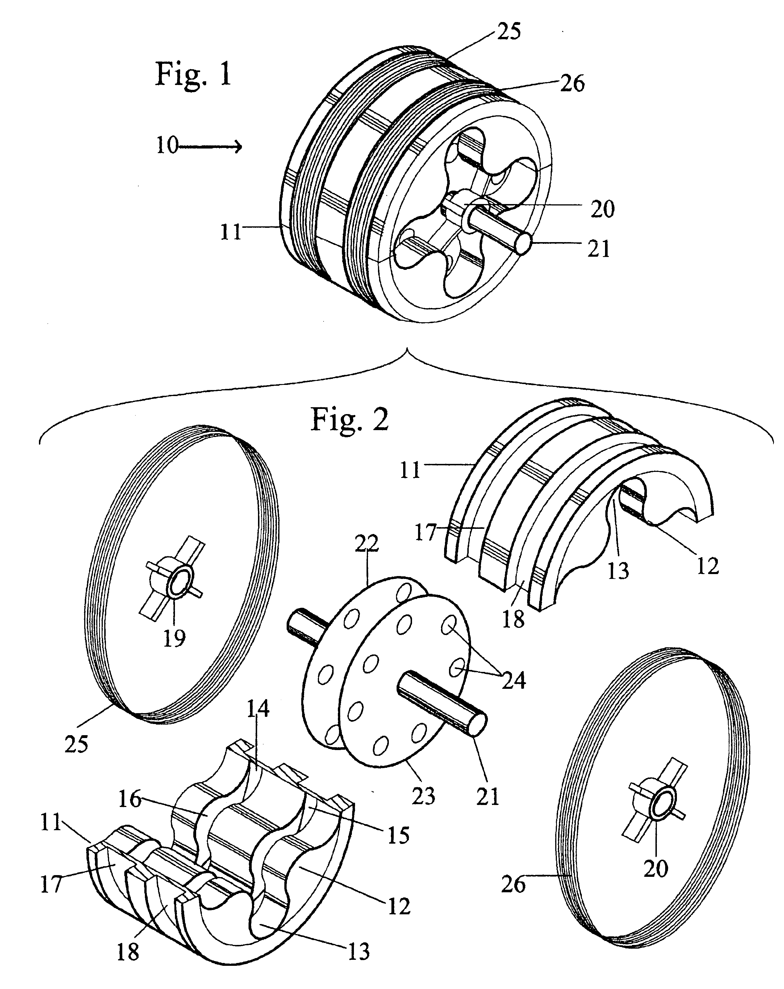
[0025]Referring now to FIG. 1, a simplified perspective view of the major structural components of the improved electric motor 10 of the present invention is illustrated. In particular, motor 10 comprises stator core 11, bearing support 20, coil 25, coil 26 and shaft member 21.

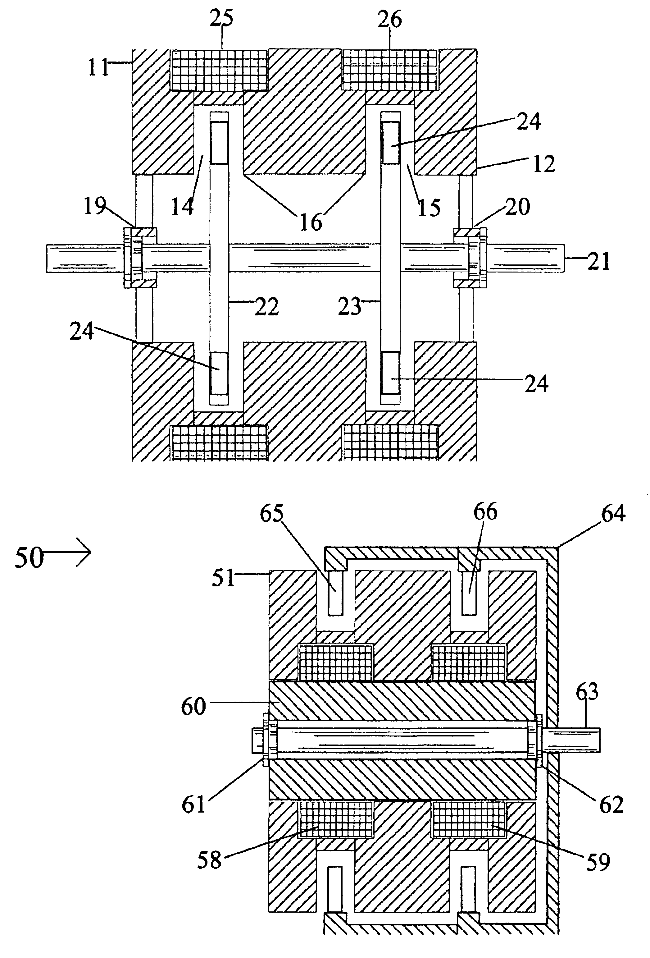
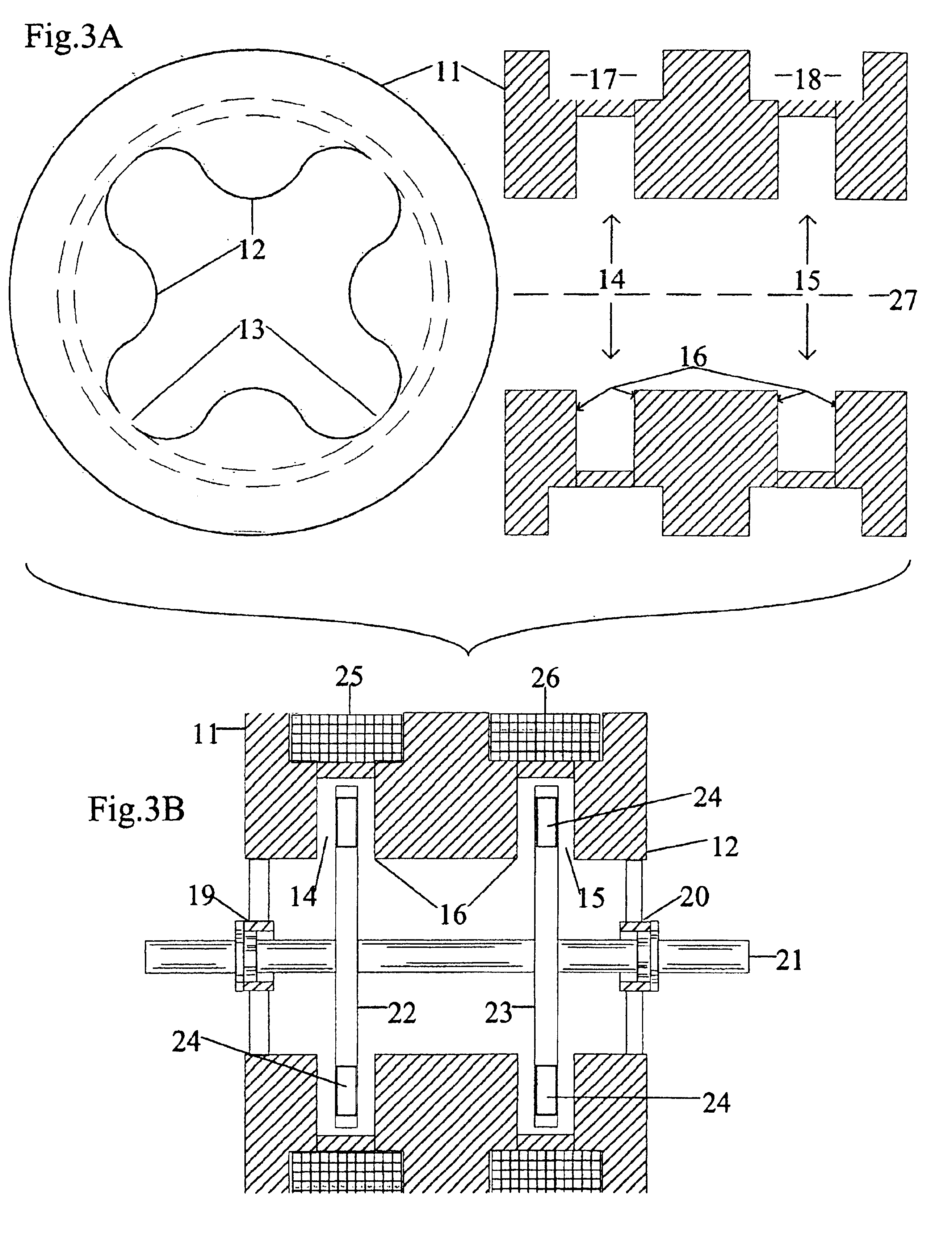
[0026]FIG. 2 is an exploded view illustrating the components forming the electric motor 10 of the present invention. In particular, motor 10 comprises cylindrical stator core 11, made of ferromagnetic material, having a series of interior corrugations forming peaks 12 and valleys 13 intersected by interior annular grooves 14 and 15, the intersections of corrugation peaks 12 and annular grooves 14 and 15 forming pole faces 16. The exterior of core 11 has exterior annular notches, or depressions, 17 and 18 formed about the circumference of core 11, notches 17 and 18 adapted to receive coils 25 and 26, respectively. Bearing supports 19 and 20 and rotor disks 22 and 23 having a plurality of permanent magnets 24 em...


PUM


Abstract

An improved electric motor design wherein the interior surface of the stator has a plurality of corrugations intersected by annular grooves formed therein and a corresponding number of rotor disks having permanent magnets secured to their outer surface, the permanent magnets being positioned to rotate within the grooves. The magnets alternate in polarity about each disk as well as being offset about the circumference from disk to disk so that one disk set will align with the pole face created by the intersection of the corrugations and the adjacent annular grooves and the other disk set will be offset from the corrugations and pole faces. Alternately energizing coils positioned within a plurality of notches formed in the outer surface of the stator with alternating current causes the magnets and their associated disks to reposition themselves in a manner that causes the motor shaft to rotate as well as shaping the core flux field for more efficient use, thereby increasing motor torque.

Description

BACKGROUND OF THE INVENTION[0001]1. Field of the Invention[0002]The present invention provides an axial flux, electromotive generating device that includes rotors having a plurality of magnets mounted thereto and a stator core assembly having a plurality of annular grooves and corrugations formed along the interior and exterior of the stator.[0003]2. Description of the Prior Art[0004]Axial flux electromotive generating devices have been widely described in the prior art. For example, U.S. Pat. No. 6,445,105 to Kliman et al describes such a device having a rotatable shaft, a rotor disk coupled to the shaft, a permanent magnet supported by the rotor disk, a stator extension positioned in parallel with the rotor disk, two molded iron pole elements attached to the stator extension and facing the permanent magnet and two electrical coils wrapped around the corresponding two molded iron pole elements.[0005]U.S. Pat. No. 6,323,576 to Applegate discloses an electromotive generator which uti...

Claims


Application Information

Patent Timeline
IPC IPC(8): H02K21/12H02K21/14H02K21/24
CPCH02K21/24H02K21/145
Inventor CHIARENZA, KEVIN J.
Owner CHIARENZA KEVIN J
Why Eureka
Try Eureka