
System, apparatus, and method for generating directional forces by introducing a controlled plasma environment into an asymmetric capacitor

a technology of asymmetric capacitors and plasma environment, which is applied in the direction of generators/motors, machines/engines, vehicle maintenance, etc., can solve the problems of fuel consumption ratio, amount of energy required to produce motive force, and imbalanced force, so as to increase the motive force and increase the plasma density

Inactive Publication Date: 2006-01-12
ROBERT CHRYSLER BRENNAN TRUSTEE FOR SDI TECH TRUST
View PDF14 Cites 4 Cited by
  • Summary
  • Abstract
  • Description
  • Claims
  • Application Information

AI Technical Summary

Benefits of technology

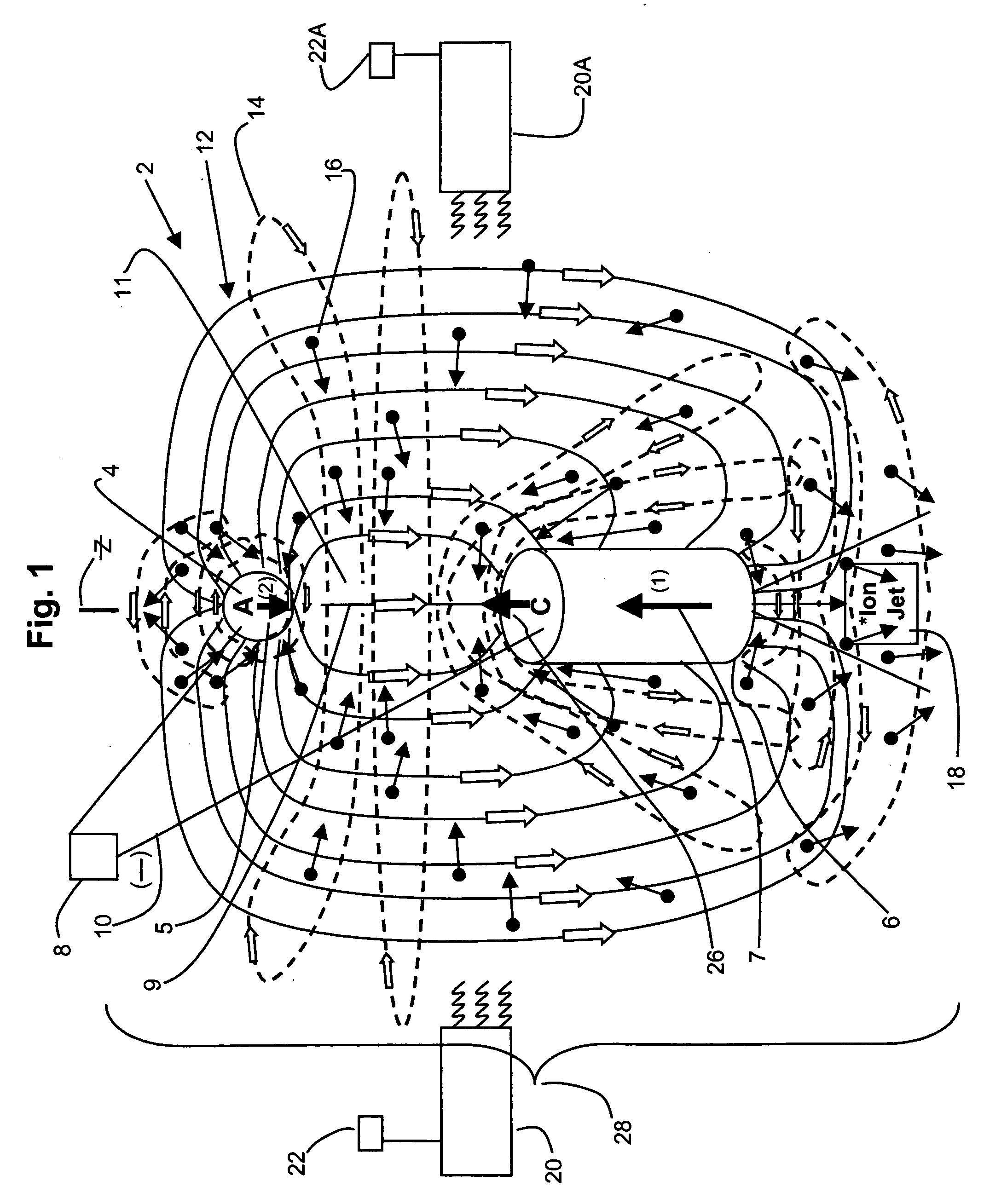
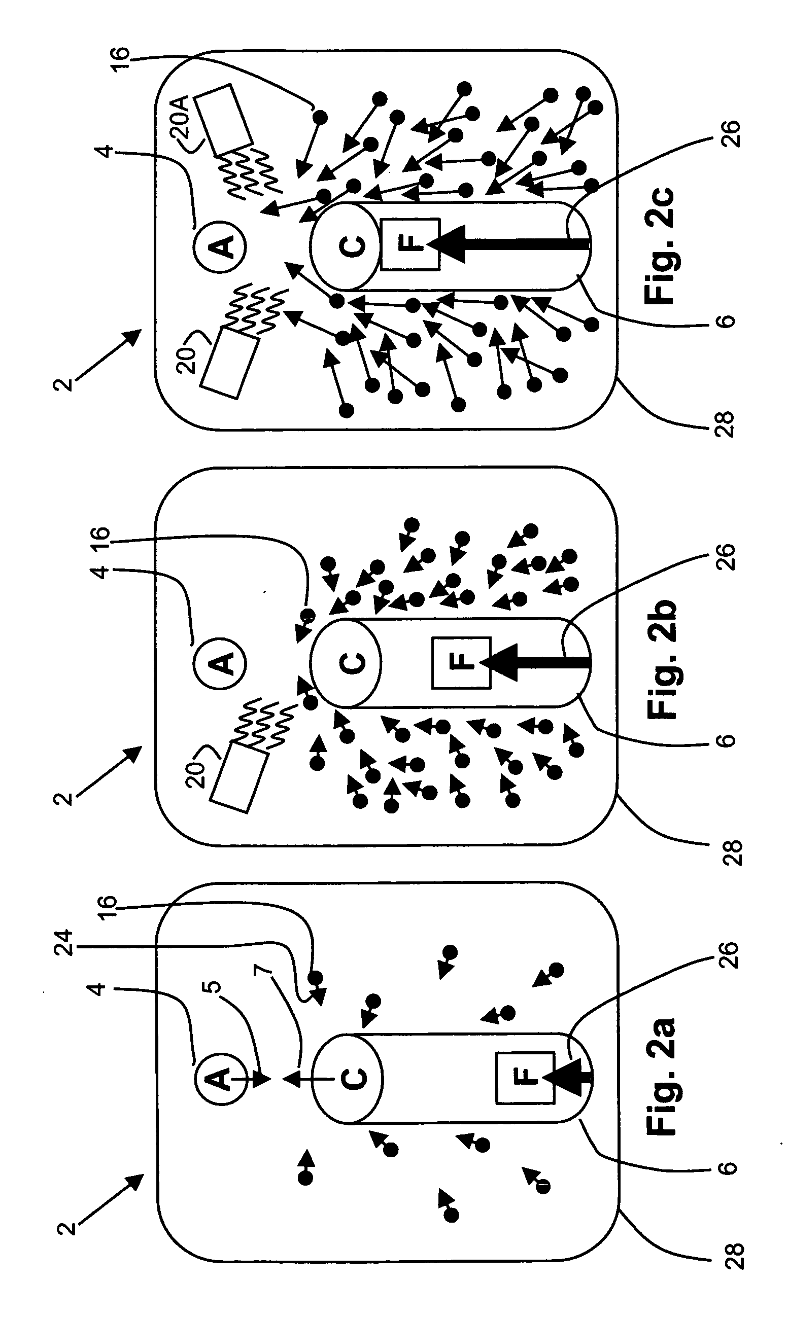
[0011] In one embodiment, the energy field is energized by applying a system to introduce a controlled plasma environment in the energy field through electromagnetic radiation, such as with a laser or an annular array of light emitting diodes (LEDs). The energy field can be energized by increasing the plasma density, plasma energy and particle velocity, or a combination thereof. Further, the plasma environment can be energized prior to developing a significant asymmetric energy field. In yet another embodiment, the present invention significantly enhances forces at substantially reduced voltage levels using the electromagnetic radiation compared to the previously required voltage levels without the electromagnetic radiation. Advantageously, the low voltage can reduce or eliminate negative secondary effects caused by the heretofore prior high voltage levels required to energize the asymmetric capacitor engine.

Problems solved by technology

The electrical field surrounding an energized asymmetric capacitor creates an imbalanced force and therefore a motive force of a small magnitude.
The challenge over the past decades has been the amount of energy required to produce the motive force, also known as thrust-to-power consumption ratio.
Although lightweight, asymmetric capacitor models have demonstrated the ability to produce enough force to overcome the effect of gravity on their own mass, the amount of energy required has been prohibitive to make practical and commercial use of this feature.
Another challenge is the “space charge limited current” saturation point (also referred to as “charged space limits”) or the limit of charged particles that a given volume of space can accommodate.
If the system is free to move, there still will be ions flowing through and around the capacitor as a result of collisions but this flow should be much weaker than that in the case of fixing the system since the ions lose their kinetic energy and momentum through collisions with the electrode surfaces.
While the general concept of asymmetric capacitors and the use of ionic forces are known, the inability to produce sufficient motive force has eliminated many potential uses.
Thus, the dilemma heretofore has been to increase the amount of conduction current in an ion processing propulsion system without increasing the power consumption, when the level of high-voltage required must be high enough to create the conduction current in the first place.
A further challenge has been the heretofore accepted high voltage input needed based on the above listed efforts and other similar efforts.
However, the high voltage input has undesirable secondary effects.

Method used


Image

  • System, apparatus, and method for generating directional forces by introducing a controlled plasma environment into an asymmetric capacitor
  • System, apparatus, and method for generating directional forces by introducing a controlled plasma environment into an asymmetric capacitor
  • System, apparatus, and method for generating directional forces by introducing a controlled plasma environment into an asymmetric capacitor

Examples


example 1

[0092] In at least one embodiment, electromagnetic radiation, such as photonic (including UV and / or IR) and RF energy can be delivered into a volume of the asymmetric capacitor system. The electrodes can be at least partially copper, aluminum, or other conductive material. One or more porous electrodes can be used to increase the total surface and the Bohm current. One or more (such as an annular array of LEDs) electromagnetic radiation sources are attached to locations above the anode, between the anode and cathode, under the cathode or any combination thereof to energize particles between the electrodes (that is at least somewhere in the surrounding fields of the electrodes). A further electromagnetic radiation source can be an RF emitter device using pulsed magnetrons with variable frequency. In some embodiments, 10 kW pulsed magnetrons with variable frequency are preferred. A commercial-off-the-shelf laser or LED array and RF device may be used. Advantageously, the method of att...


PUM


Abstract

The present invention provides method, apparatus, and system that generates and uses a motive and other force by introducing a plasma environment into an asymmetric capacitor, resulting in a significant gain in force. In one embodiment, the energy field is energized by applying a system to increase a plasma density by ionizing the plasma environment in the energy field through electromagnetic radiation, by increasing the plasma temperature, or some combination thereof. The invention also generates a flow of energy or plasma directed outward from the apparatus. The present invention can also provide the motive forces at a variety of angles at substantially reduced voltage levels.

Description

[0001] This application is a continuation-in-part application of U.S. patent application Ser. No. 11 / 135,596, filed May 23, 2005, which claims the benefit of U.S. Provisional Application No. 60 / 573,884, filed May 24, 2004.FIELD OF THE INVENTION [0002] The present invention relates to asymmetrical capacitors. More particularly, the invention relates to generating a force using asymmetrical capacitors by introducing a controlled plasma environment. BACKGROUND OF THE INVENTION [0003] Asymmetric capacitors are known to exhibit a net force when sufficient power is applied. An asymmetric capacitor is generally a capacitor that has geometrically dissimilar electrode surface areas. The electrical field surrounding an energized asymmetric capacitor creates an imbalanced force and therefore a motive force of a small magnitude. The challenge over the past decades has been the amount of energy required to produce the motive force, also known as thrust-to-power consumption ratio. Although lightw...

Claims


Application Information

Patent Timeline
Patent Type & Authority Applications(United States)
IPC IPC(8): B60S9/21H02J1/00H02N1/00
CPCF03H1/00H02N1/002F03H99/00
Inventor BRENNAN, ROBERT CHRYSLERPENNY, L. STUART
Owner ROBERT CHRYSLER BRENNAN TRUSTEE FOR SDI TECH TRUST
Learn More