Water augmented regeneration (WAR) turbine system and cycle

a technology of water augmented regeneration and turbine system, which is applied in the direction of hot gas positive displacement engine plants, machines/engines, engine fuctions, etc., can solve the problems of increased nox emissions and destabilization of combustion flames, and achieve substantial heat rate improvement and enhanced motive force

Active Publication Date: 2005-08-11
SIEMENS ENERGY INC
View PDF6 Cites 19 Cited by
  • Summary
  • Abstract
  • Description
  • Claims
  • Application Information

AI Technical Summary

Benefits of technology

[0006] A gas turbine system includes a compressor for receiving air and producing compressor discharge air, a combustor for combusting an oxygen comprising gas flow including the discharge air and a fuel into a hot gas flow, and a turbine expander generating output power from the hot gas flow and providing a hot exhaust gas flow. An extractor is provided for splitting the discharge air into a direct flow portion which directly reaches the combustor and an indirect flow portion. A mixing device receives the indirect flow portion and mixes it with a water flow, either in the form of water or steam, to produce a water enhanced indirect flow portion having an enhanced motive force. A recuperative heat exchanger heats the water enhanced indirect flow portion using heat from at least a portion of the hot exhaust gas flow. The heated water enhanced indirect flow portion is then reintroduced into the oxygen comprising gas flow. The system provides a substantial heat rate improvement over both a dry system or a wet compression system.

Problems solved by technology

However, a decrease in compressor discharge air temperature can result in a destabilization of the combustion flame.
Combustion stabilization can be achieved by retuning the combustion system, however this typically results in increased NOx emissions.

Method used


Image

  • Water augmented regeneration (WAR) turbine system and cycle
  • Water augmented regeneration (WAR) turbine system and cycle
  • Water augmented regeneration (WAR) turbine system and cycle

Examples


case 1

[0053] 10%×665.0=66.5 lbm / sec

case 2

[0054] 25%×665.0=166.3 lbm / sec

case 3

[0055] 50%×665.0=332.5 lbm / sec

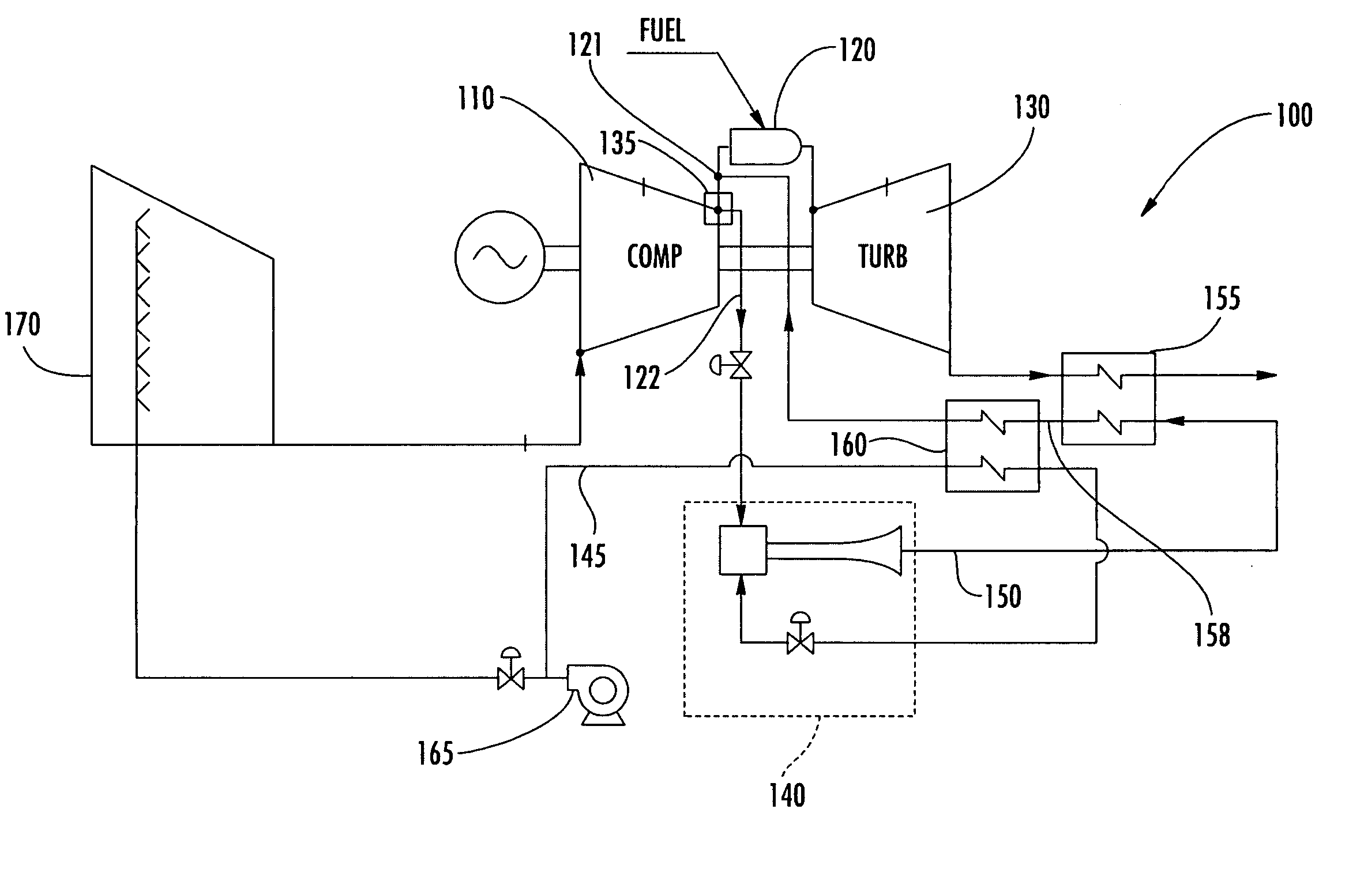
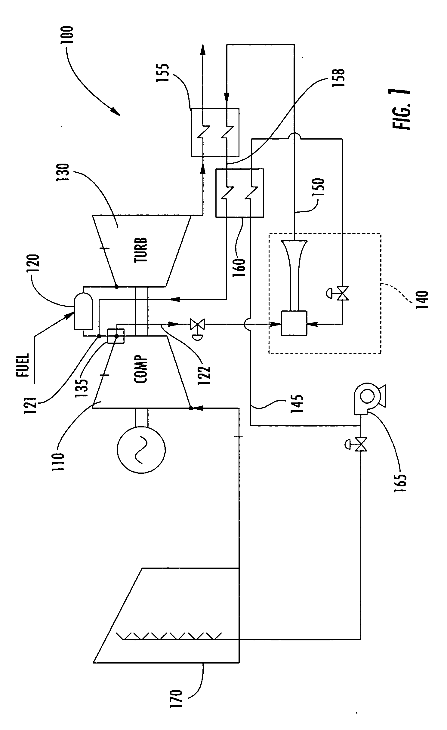
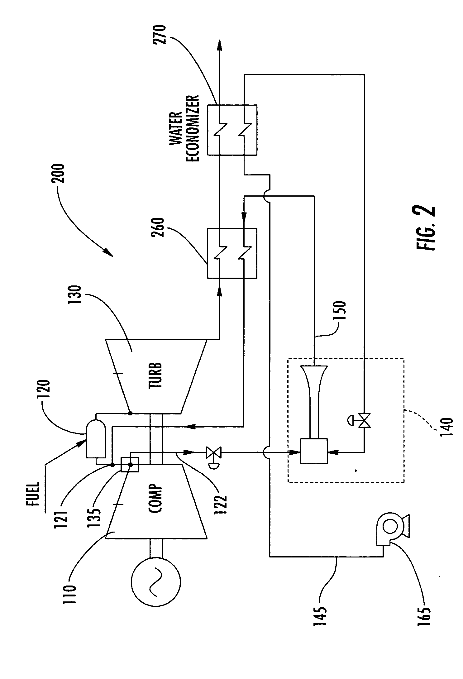
[0056] The following major assumptions were used in the analysis (refer to system 500 shown in FIG. 5 for point locations referred to below):

[0057] Pressure drop from point A to point B is 10 psi.

[0058] Isentropic efficiency of the booster pump 540 is ηB=90%.

[0059] Pressure drop from point C to point D is 5 psi.

[0060] Pressure drop from point D to point E (across heat exchanger) is 10 psi.

[0061] Heat exchanger effectiveness is ε=0.8.

[0062] Pressure drop from point E to point F is 5 psi.

[0063] Warm air from the regenerator is thoroughly mixed with air directly from the compressor discharge before entering the combustion chamber.

[0064] For the combustor heat balance, it was assumed that no heat was lost to the surroundings (no “heat-up” of combustor shell air).

[0065] Energy added from combustion was assumed to be equal to {dot over (m)}fuel LHV′, where LHV′=LHV+hfuel.

[0066] Steady state is assumed everywhere.

[0067] All gases are assumed to be ...


PUM


Abstract

A gas turbine system (100) includes a compressor (110) for receiving air and producing compressor discharge air, a combustor (120) for combusting an oxygen comprising gas flow including the discharge air and a fuel into a hot gas flow, and a turbine expander (130) generating output power from the hot gas flow and providing a hot exhaust gas flow. An extractor (135) is provided for splitting the discharge air into a direct flow portion (121) which directly reaches the combustor (120) and an indirect flow portion (122). A mixing device (140) receives the indirect flow portion (122) and mixes it with a water flow (145), either in the form of water or steam, to produce a water enhanced indirect flow portion (150). A recuperative heat exchanger (155) heats the water enhanced indirect flow portion (150) using heat from at least a portion of the hot exhaust gas flow. The heated water enhanced indirect flow portion (158) is then reintroduced into the oxygen comprising gas flow.

Description

CROSS-REFERENCE TO RELATED APPLICATIONS [0001] This application claims the benefit of Provisional Patent Application No. 60 / 542,939 filed on Feb. 9, 2004, which is hereby incorporated by reference in its entirety into the current application.FIELD OF THE INVENTION [0002] The invention relates to gas turbines, and more specifically to turbines utilizing water augmented regeneration cycles. BACKGROUND OF THE INVENTION [0003] Gas turbines are used in a variety of applications. Gas turbines have a compressor section for compressing inlet air, a combustion section for combining the compressed inlet air with fuel and oxidizing that fuel, and a turbine section where the energy from the hot gas produced by the oxidation of the fuel is converted into work. Usually, natural gas (mostly methane), kerosene, or synthetic gas (such as carbon monoxide) is fed as fuel to the combustion section, but other fuels could be used. The rotor, defined by a rotor shaft, attached turbine section rotor blades...

Claims


Application Information

Patent Timeline
Patent Type & Authority Applications(United States)
IPC IPC(8): F01K21/04F02C3/30F02C7/141F02C7/143
CPCF01K21/047F02C3/30F05D2260/601F02C7/1435F02C7/141
Inventor CARLSON, CHARLES A. JR.DOVALI-SOLIS, FRANCISCOPLANT, ADAM
Owner SIEMENS ENERGY INC
Why Eureka
Try Eureka