Magnetic field detection circuit using magnetic impedance device

a detection circuit and magnetic impedance technology, applied in the direction of galvano-magnetic devices, magnetic measurements, instruments, etc., can solve the problems of several milliampere errors, calculation using formulas inevitably involving errors, and affecting the detection accuracy of bearings or electric current sensors. , to achieve the effect of allowing nil-point setting, low cost and simple configuration

Inactive Publication Date: 2005-05-24
CANON DENSHI KK
View PDF3 Cites 9 Cited by
  • Summary
  • Abstract
  • Description
  • Claims
  • Application Information

AI Technical Summary

Benefits of technology

[0015]In view of the above identified problems, it is therefore an object of the present invention to provide a low cost magnetic field detection circuit that has a simple configuration and allows nil-point setting on a stable basis.

Problems solved by technology

If the nil-point setting is not in place, the detection accuracy of the bearing or electric current sensor will be adversely affected to a large extent.
However, if the outputs Vxo, Vyo for a nil-magnetic field are not accurate, the calculation using the formula inevitably comes to involve errors.
In the case of an electric current sensor, again, if the nil-point setting is not reliable, there can easily arise an error of several milliamperes (mA) in response to an output error of several milligausses (mG) when transforming the magnetic field from an electric current line into a voltage and evaluating the electric current that may be a DC as weak as tens of several milliamperes (mA).
Under such circumstances, it is difficult to manually regulate the nil-point voltage.
While it is theoretically possible to incorporate a circuit for automatically regulating the nil-point voltage, the overall circuit configuration will become highly complex and the cost will become prohibitive.

Method used


Image

  • Magnetic field detection circuit using magnetic impedance device
  • Magnetic field detection circuit using magnetic impedance device
  • Magnetic field detection circuit using magnetic impedance device

Examples


Embodiment Construction

[0029]Now, the present invention will be described in greater detail by referring to FIGS. 1 through 9 of the accompanying drawings that illustrate preferred embodiments of the invention.

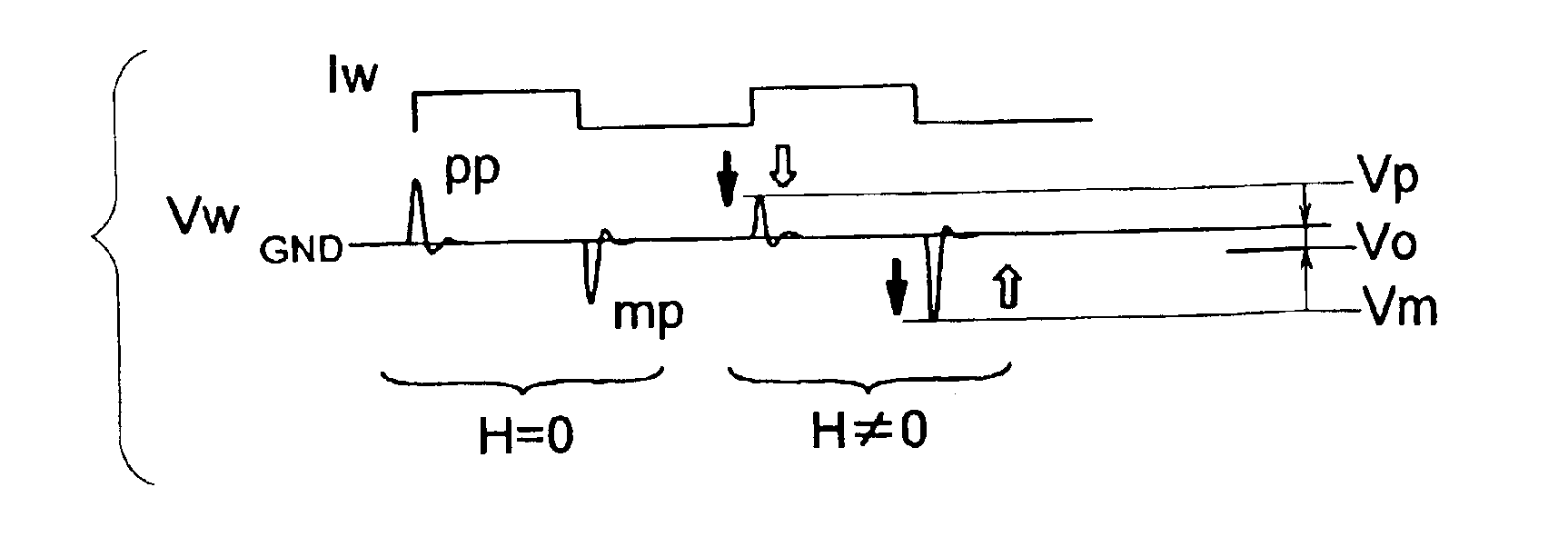
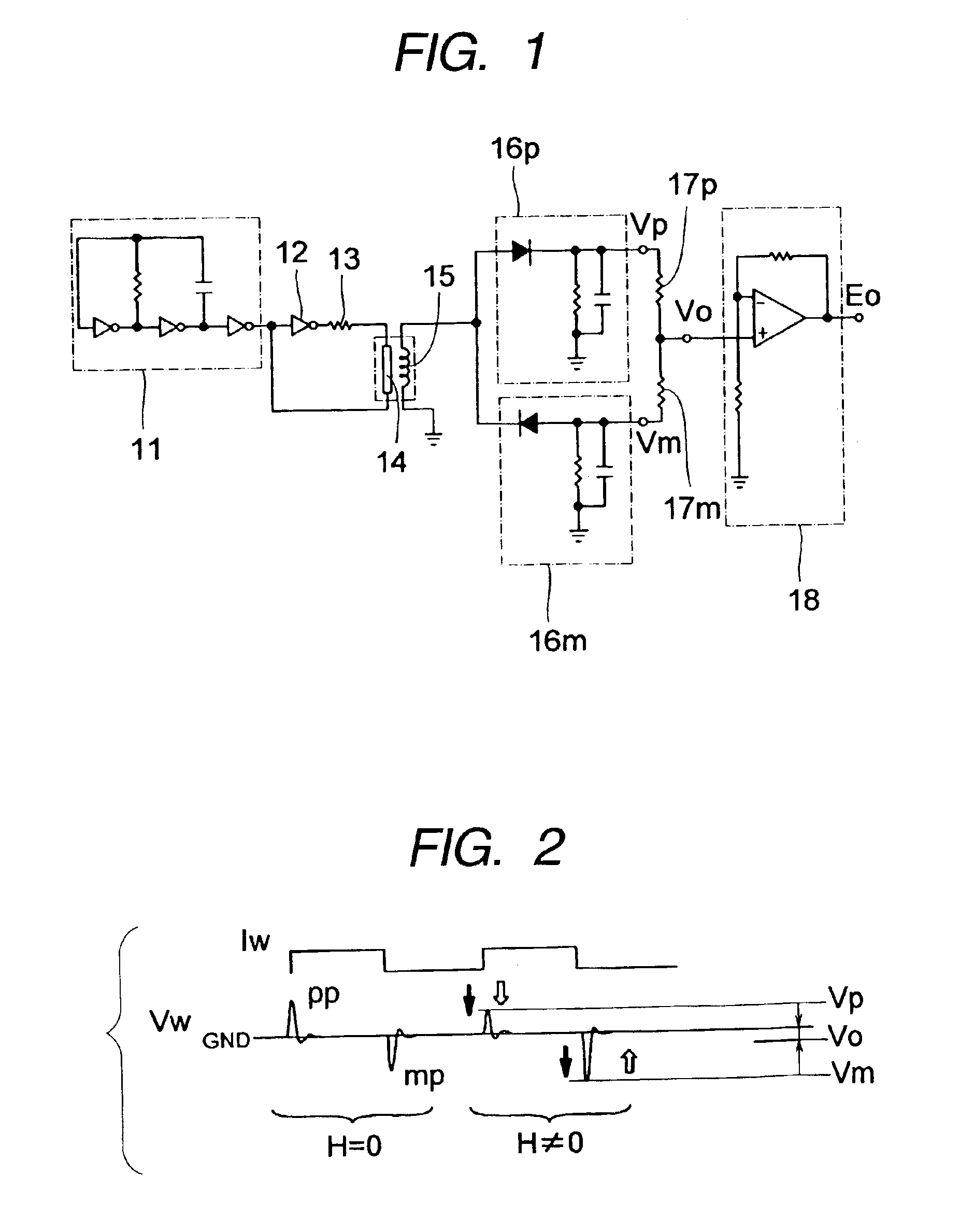
[0030]FIG. 1 is a schematic circuit diagram of an embodiment of magnetic field detection circuit according to the invention and comprising a magnetic impedance device. An oscillation circuit 11 surrounded by broken lines in FIG. 1 is formed by using C-MOS inverters and a CR circuit as in the case of the conventional one illustrated in FIG. 10. The output side of the oscillation circuit 11 is connected to one of the terminals of MI device 14 by way of a C-MOS inverter 12 and a current regulating resistor 13, while the other terminal of the MI device 14 is connected to the input side of the inverter 12. With the above described connection arrangement, an electric current adapted to swing symmetrically to the positive side and the negative side is applied to the MI device 14.

[0031]It is desirable that ...


PUM


Abstract

A magnetic field detection circuit comprises a magnetic impedance device, a detection coil wound around or arranged close to the impedance device, an electric current application circuit for applying a pulse-shaped high frequency electric current substantially equally swinging to the positive side and the negative side to the magnetic impedance device, and a detection circuit for detecting a voltage generated in the detection coil in response to rises and falls of the applied pulse-shaped electric current and outputting a signal corresponding to the intensity of the external magnetic field on the basis of the outcome of the detection. The magnetic field detection circuit can provide nil-point setting on a stable basis by means of a simple circuit arrangement at low cost.

Description

BACKGROUND OF THE INVENTION[0001]1. Field of the Invention[0002]This invention relates to a magnetic field detection circuit for detecting the intensity of the external magnetic field by using a magnetic impedance device whose impedance changes as a function of the external magnetic field in a state where a high frequency electric current is applied. More particularly, the present invention relates to a magnetic field detection circuit for highly sensitively and accurately detecting a very weak magnetic field generated by the terrestrial magnetism or a very weak electric current.[0003]2. Related Background Art[0004]In recent years, bearing sensors adapted to detect the terrestrial magnetism and electric current sensors capable of detecting a very weak electric current have come to be required to highly sensitively and accurately detect a very weak magnetic field so as to broaden the scope of application. Magnetic impedance devices (to be referred to as MI devices hereinafter) have b...

Claims


Application Information

Patent Timeline
Patent Type & Authority Patents(United States)
IPC IPC(8): G01R33/028G01R33/02H01L43/00
CPCG01R33/028
Inventor KAWASE, MASAHIRO
Owner CANON DENSHI KK
Why Eureka
Try Eureka