
Remotely adjustable bandpass filter

Inactive Publication Date: 2005-05-24
APPLE INC
View PDF26 Cites 10 Cited by
  • Summary
  • Abstract
  • Description
  • Claims
  • Application Information

AI Technical Summary

Benefits of technology

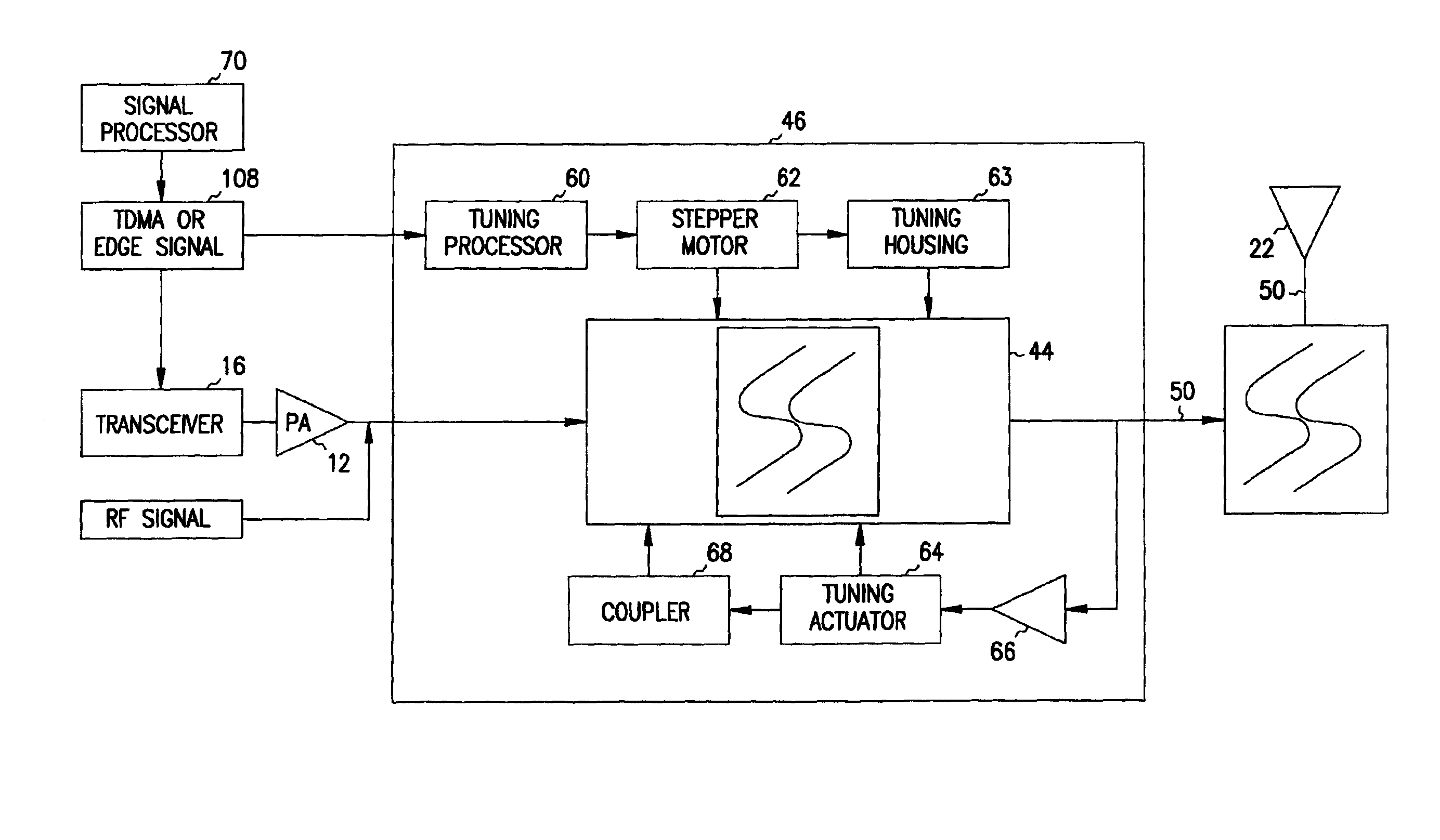
[0006]Remote tuning of a plurality of bandpass cavity filters is provided to accommodate transmission of different frequencies required by different communication protocols. Remotely controllable actuators are provided to alter the cavity size of the filters or other characteristics to alter the bandpass characteristics. In one embodiment, a stepper motor is used to provide lateral movement of a tuning plate to alter the size of the cavity. The neck of the cavity is also changed in length in another embodiment through the, use of a tuning motor. A feedback loop is used to provide fine tuning of the length of the neck in response to changes due to temperature and vibration to offer maximum propagation of the signal to be transmitted.
[0007]In a further embodiment, a coupling tuner is used to adjust to the resulting change in Q to the cavity. A tuning processor is used to receive signals from a remote location identifying the desired characteristics of the filter. The signals may be provided via the communication signal, such as TDMA or EDGE signals, or may be separately transmitted and received. The tuning processor then controls the actuators to alter the filters to the desired frequencies. Multiple frequencies may be easily accommodated as desired.

Problems solved by technology

The foregoing presents a problem, inasmuch as the base stations of cellular telephone systems are usually large in number and are often remotely located from the business or service offices of the system's service provider.
Moreover, these base stations are usually unmanned.

Method used


Image

  • Remotely adjustable bandpass filter
  • Remotely adjustable bandpass filter
  • Remotely adjustable bandpass filter

Examples


Embodiment Construction

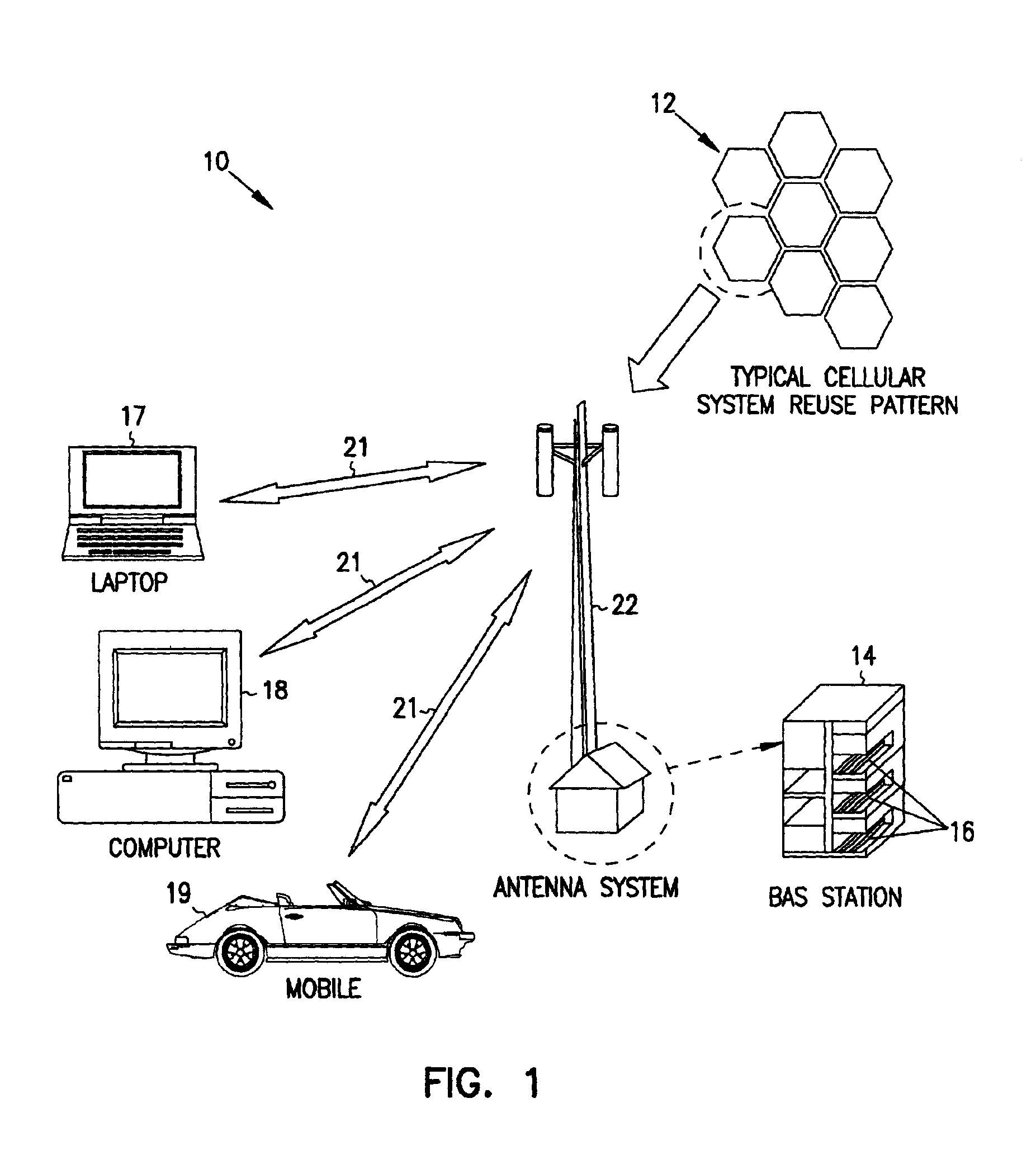
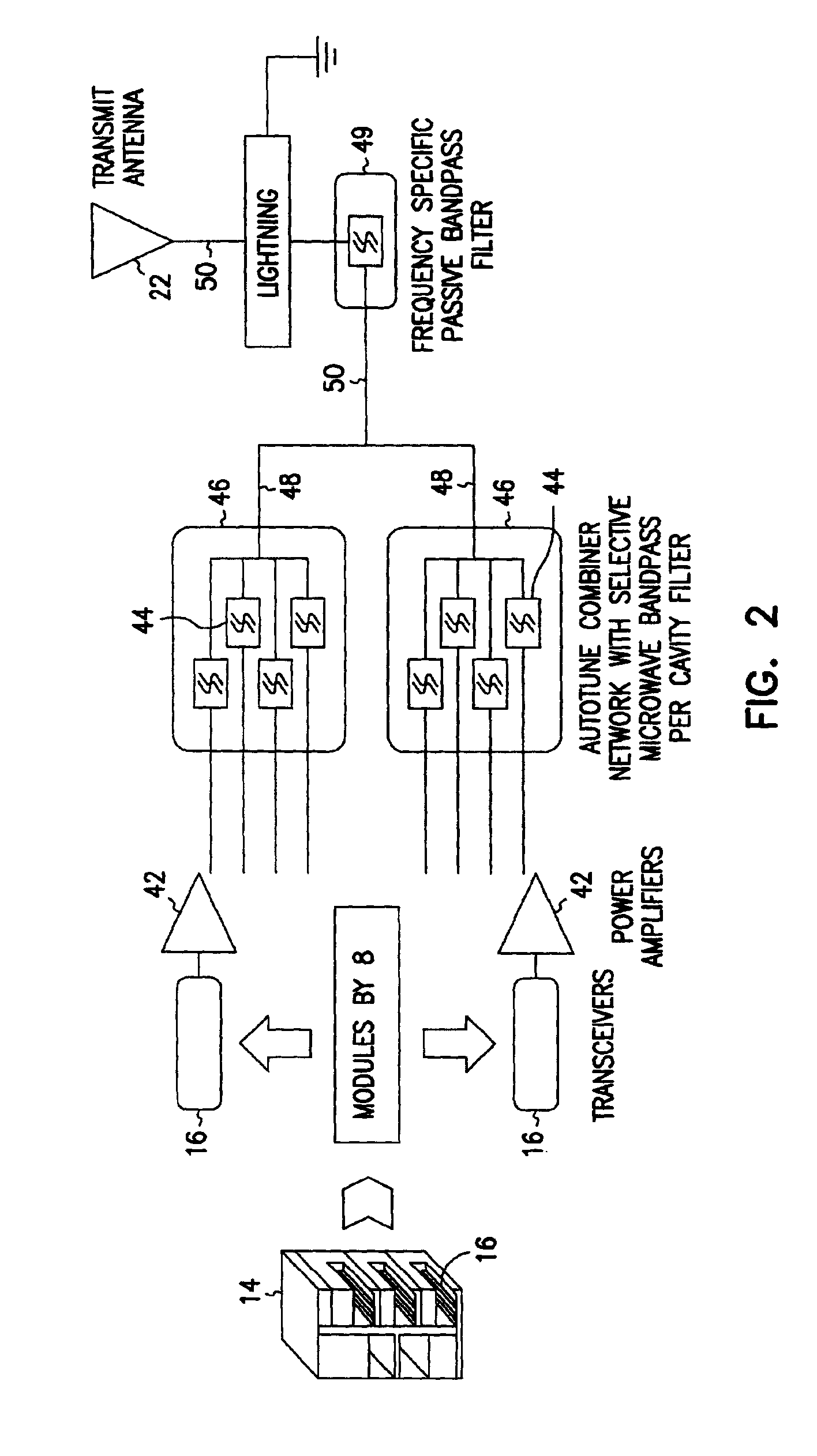
[0012]In FIGS. 1 and 2, generalized depictions of a cellular telephone system 10 are shown that utilize the principles of the present invention. The system 10 includes numerous cells 12 each of which is serviced by one or more base stations 14. There are numerous ways in which the cells 12, which are usually considered to be circular or hexagonal in shape, may be defined and located relative to each other. Typically, each base station 14 is located at the center of its cell 12 and contains multiple transceivers 16 capable of transmitting signals to and receiving signals from subscribers' telephones, personal computers and laptop computers (“units”) 17, 18 and 19 that are located within, and more or less randomly scattered about, the cells 12. These communications between the transceivers 16 and the units 17-19 are carried out via self-contained unit antennae (not shown) and antennae 22 associated with the transceivers 16 in the base station 14 of each cell 12 and co-located therewit...


PUM


Abstract

Remotely controllable actuators are provided to alter the cavity size of bandpass cavity filters to alter the bandpass characteristics. In one embodiment, a stepper motor is used to provide lateral movement of a tuning plate to alter the size of the cavity. The neck of the cavity is also changed in length through the use of a tuning motor. A feedback loop is used to provide fine tuning of the length of the neck in response to changes due to temperature and vibration to offer maximum propagation of the signal to be transmitted. A coupling tuner is used to adjust to the resulting change in Q to the cavity. A tuning processor is used to receive signals from a remote location identifying the desired characteristics of the filter.

Description

FIELD OF THE INVENTION[0001]The present invention relates to a remotely operable bandpass filter and, more particularly, to a bandpass filter that is remotely adjustable to selectively pass microwave signals from one of several transceivers of a cellular telephone base station pursuant to cellular telephone traffic loads or customer demand in its cell.BACKGROUND OF THE INVENTION[0002]Cellular or radio telephony systems utilize numerous microwave devices, such as waveguides, bandpass filters, couplers, combiners or diplexers, attenuators and resonators. Such a device exhibits selected responses to specific input signals, and these responses may be realized either by selecting and using a device having the desired response or by changing the characteristics of a single device until the desired response is achieved. Changing the characteristics of a resonant RF cavity, such as a bandpass filter, involves altering the electrical and / or magnetic characteristics thereof. For example, both...

Claims


Application Information

Patent Timeline
IPC IPC(8): H04B1/04H04B1/40
CPCH03J1/0008H04B1/04H04B1/406
Inventor FAYESKI, ERIC S.CARLSON, BRAD W.
Owner APPLE INC
Learn More