System for aiding in the design of combinatorial logic and sequential state machines

Active Publication Date: 2005-05-24
MCFARLAND M DAVID
View PDF4 Cites 20 Cited by
  • Summary
  • Abstract
  • Description
  • Claims
  • Application Information

AI Technical Summary

Benefits of technology

[0007]The method also, preferably, comprises a step of visually displaying the combination maps and the relationship between combination maps of preceding and successive fields on a computer monitor. The step of visually displaying the combination maps, preferably, includes a step of collapsing selected fields and the maps associated therewith (i.e., selected by a user) on the display of the computer monitor, thereby reducing clutter on the display of the computer monitor and enabling the use of transforms having a large number of input variables without becoming unwieldy. The collapsing of selected fields and maps on the display enables the selected display of only combinations of those input variables that effect the value of selected outputs. The display of combination maps and the collapsing of selected maps also more easily enables a user to insure that all input variable combinations have been considered and that only one transform value has been assigned to each of the combinations. Overall, such display, facilitates the design and analysis of combinational logic circuits and sequential state machines and enhances a designer's understanding and control of logic transforms.
[0008]The method further, preferably, comprises steps of encoding the transform in a linear array and storing the encoded transform in successive storage locations. Such encoding minimizes the storage capacity required to store the transform, thereby enabling the method to be employed on a computer, or similar device, having limited storage capacity. Additionally, the method, preferably, comprises a step of restricting output changes to adjacent values where only one output bit changes for each change in an input combination. By so restricting output changes, a logic device implementing the transform will operate faster.
[0013]Still another object of the present invention is to reduce display clutter when displaying a mathematical transform between a binary output variable and a large number of binary input variables.
[0016]Still another object of the present invention is to reduce the amount of storage capacity required for the storage of a transform between a binary output variable and a set of binary input variables.

Problems solved by technology

Unfortunately, these representation techniques are found to be suitable, generally, only when the number of input variables is small (e.g., six or less) because the number of tables or maps becomes unwieldy with a large number of input variables, thereby increasing the possibility for errors.

Method used


Image

  • System for aiding in the design of combinatorial logic and sequential state machines
  • System for aiding in the design of combinatorial logic and sequential state machines
  • System for aiding in the design of combinatorial logic and sequential state machines

Examples


Embodiment Construction

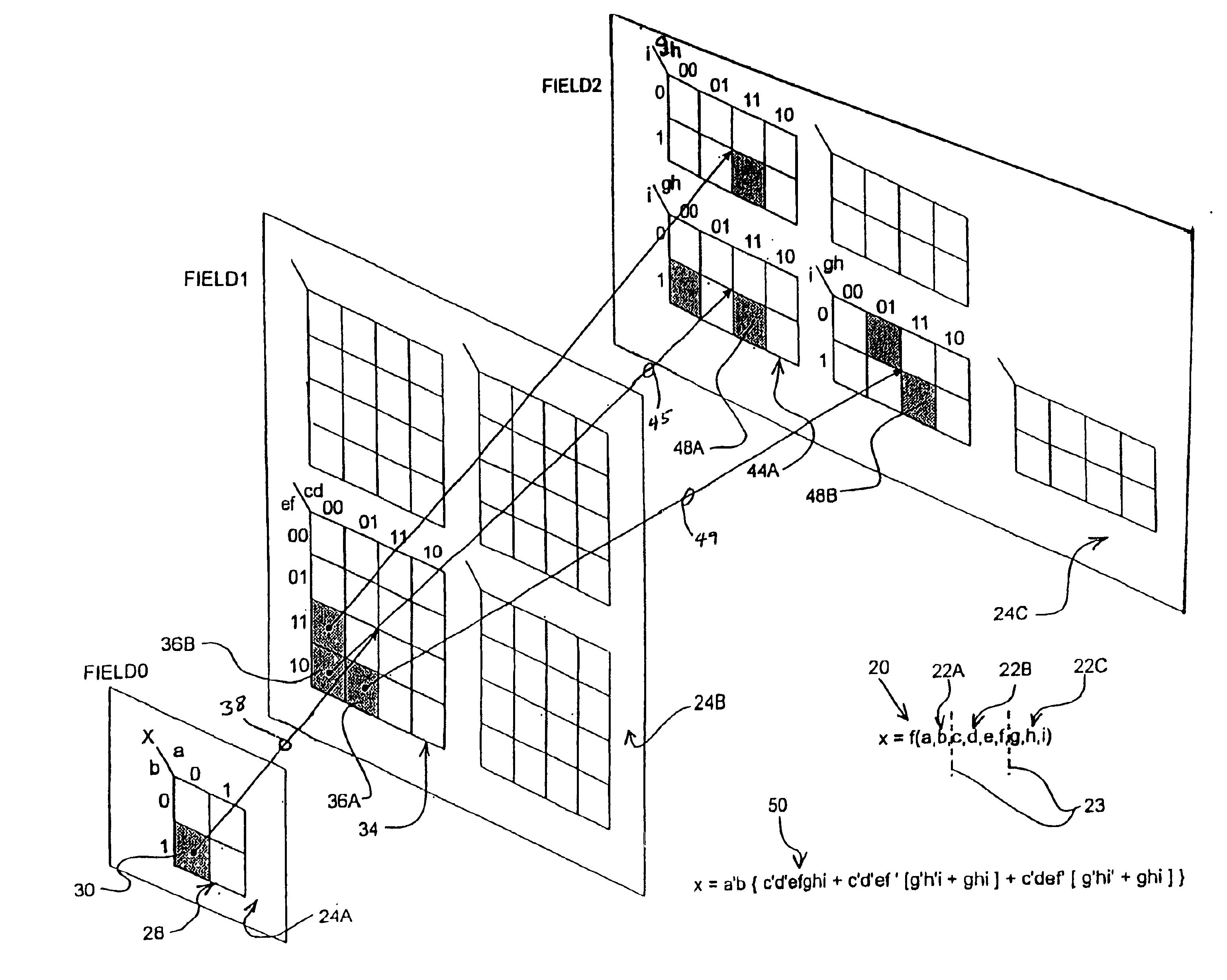
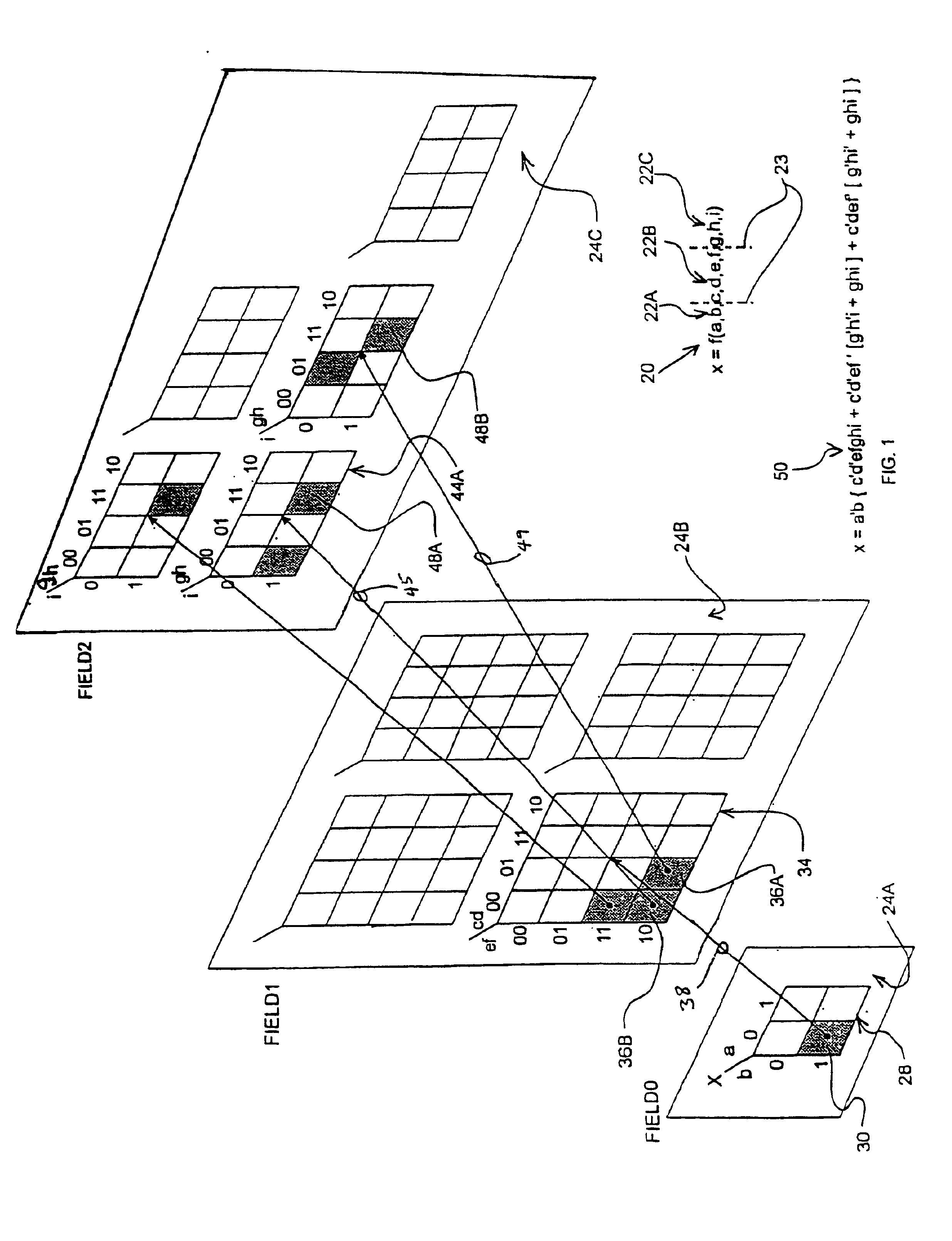
[0041]Referring now to the drawings, in which like numerals represent like components or steps throughout the several views, FIG. 1 displays a pictorial illustration of a method, in accordance with a preferred embodiment of the present invention, of representing a transform (also referred to herein as a “function”) 20 which relates a binary output variable, x, to a plurality of binary input variables, a-i. It should be understood that, as used herein, the term “input variables” refers, for example and not limitation, to input signals to a combinational circuit or to present flip-flop states in a sequential state machine. Similarly, it should be understood that, as used herein, the term “output variables” refers respectively, for example and not limitation, to a combinational circuit output signal or a flip-flop next state which may be expressed, or modeled, as a transform of a plurality of such input variables.

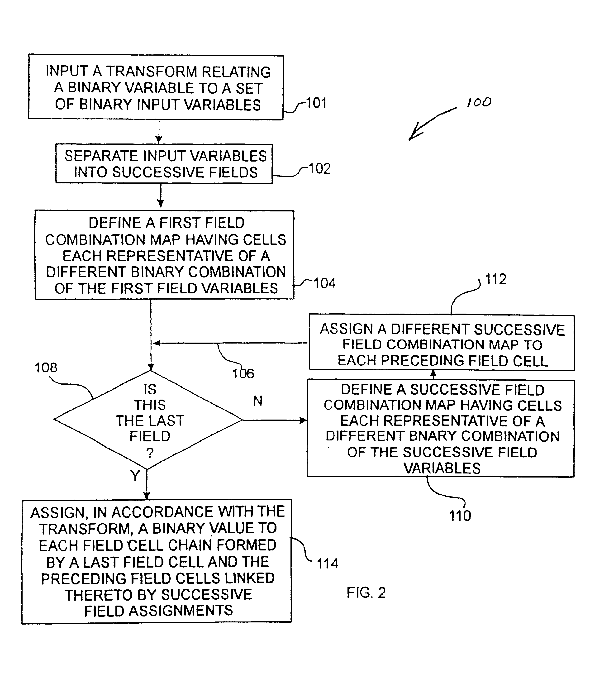
[0042]According to the method, the input variables have been separated in...


PUM


Abstract

A computer software tool for aiding in the design of combinatorial logic and sequential state machines comprising, according to the preferred embodiment, an apparatus and methods for representing and displaying a mathematical transform between a binary output variable and a set of binary input variables. The apparatus includes a computer software program which performs a method having the steps of separating input variables of a transform into successive fields, providing field combination maps having cells representative of binary combinations of field variables, assigning field combination maps of successive fields to each preceding field cell, and assigning binary values to field cell chains formed thereby. The computer software program also enables the visual display, on the display of a computer monitor, of the combination maps and the relationship between combination maps of preceding and successive fields. The process of visually displaying the combination maps includes a step of collapsing selected fields and maps associated therewith to reduce clutter on the display and to enable the use of transforms having a large number of input variables without becoming unwieldy. The collapsing of selected fields and maps on the display also enables the selected display of only combinations of those input variables that effect the value of selected outputs. The display of combination maps and the collapsing of selected maps, in addition, more easily enables a user to insure that all input variable combinations have been considered and that only one transform value has been assigned to each of the combinations.

Description

CROSS REFERENCE TO RELATED APPLICATION[0001]This application claims priority, under 35 U.S.C. § 119(e), on U.S. provisional patent application Ser. No. 60 / 172,829 which was filed Dec. 20, 1999.FIELD OF THE INVENTION[0002]The present invention relates, generally, to the field of tools for aiding in the design of combinatorial logic and sequential state machines and, in its preferred embodiments, to the field of computer software and methods for representing and displaying a transform between a binary variable and a set of binary input variables.BACKGROUND OF THE INVENTION[0003]Modern digital logic design and analysis often requires the design of combinatorial logic and sequential state machines. The design and analysis process, typically, includes a step of expressing or modeling binary output variables as mathematical transforms or functions of input binary variables. For instance, binary output variables representative of circuit outputs or flip-flop next states may be modeled as m...

Claims


Application Information

Patent Timeline
IPC IPC(8): G06F17/50
CPCG06F17/505G06F30/327
Inventor MCFARLAND, M. DAVID
Owner MCFARLAND M DAVID
Why Eureka
Try Eureka