Mounting assembly and method

a technology of mounting assembly and mounting device, which is applied in the direction of gas/liquid distribution and storage, cleaning of hollow objects, water supply installation, etc., can solve the problems of assembly seizing, difficult to achieve a constant projection distance for the part of the apparatus protruding from the front of the wall, and almost impossible for a user to get access to the nut to tighten

Inactive Publication Date: 2005-05-31
MARKS KIPLEY ROYDON
View PDF8 Cites 6 Cited by
  • Summary
  • Abstract
  • Description
  • Claims
  • Application Information

AI Technical Summary

Benefits of technology

[0010]a rear nut for contacting a rear surface of the wall and having a thread thereon adapted to engage with a corresponding thread on the sleeve, the rear nut having movement means which allow the nut to move axially relative to the object, but substantially prevent rotation of the rear nut relative to the object, and
[0024]In a further aspect the invention provides a valve having a housing with an inlet port and an outlet port, a valve member within the housing, the valve member including a control stem for a user to manipulate the valve member, the valve member being capable of being disposed in a first position to allow flow of a liquid from the inlet port to the outlet port and a second position to substantially prevent a liquid from flowing from the inlet port to the outlet port, the valve member including a housing sealing surface and the valve housing including a valve member sealing surface, the sealing surfaces being selectively engaged with each other in use to provide a seal between the valve member and the housing when the valve member is in the second position, and non-sealing surfaces adjacent to the sealing surfaces of the valve member or the housing having a relief means to allow matter entrained in the liquid which passes through the valve when the valve member is being manipulated between the first or second positions to escape from surfaces between the valve housing and the valve member to thereby prevent the valve from seizing.

Problems solved by technology

It is difficult to achieve a constant projection distance for the part of the apparatus protruding from the front of the wall.
However, in many wall mounted assemblies, particularly in the case of valve assemblies, the size and position of the valve on the rear side of the wall is such that it can be almost impossible for a user to get access to the nut to tighten it.
Also, in valve arrangements that are intended to operate using domestic water supplies, particularly for diverter valve assemblies, the assemblies are prone to seizing as a result of foreign matter, such as dirt particles, in the water becoming wedged between sealing faces of the valve members,

Method used


Image

  • Mounting assembly and method
  • Mounting assembly and method
  • Mounting assembly and method

Examples


Embodiment Construction

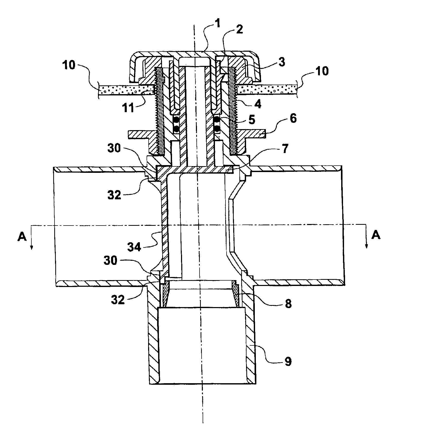
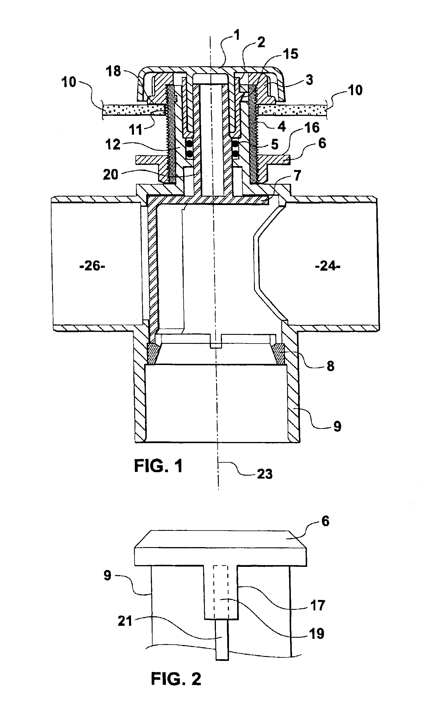
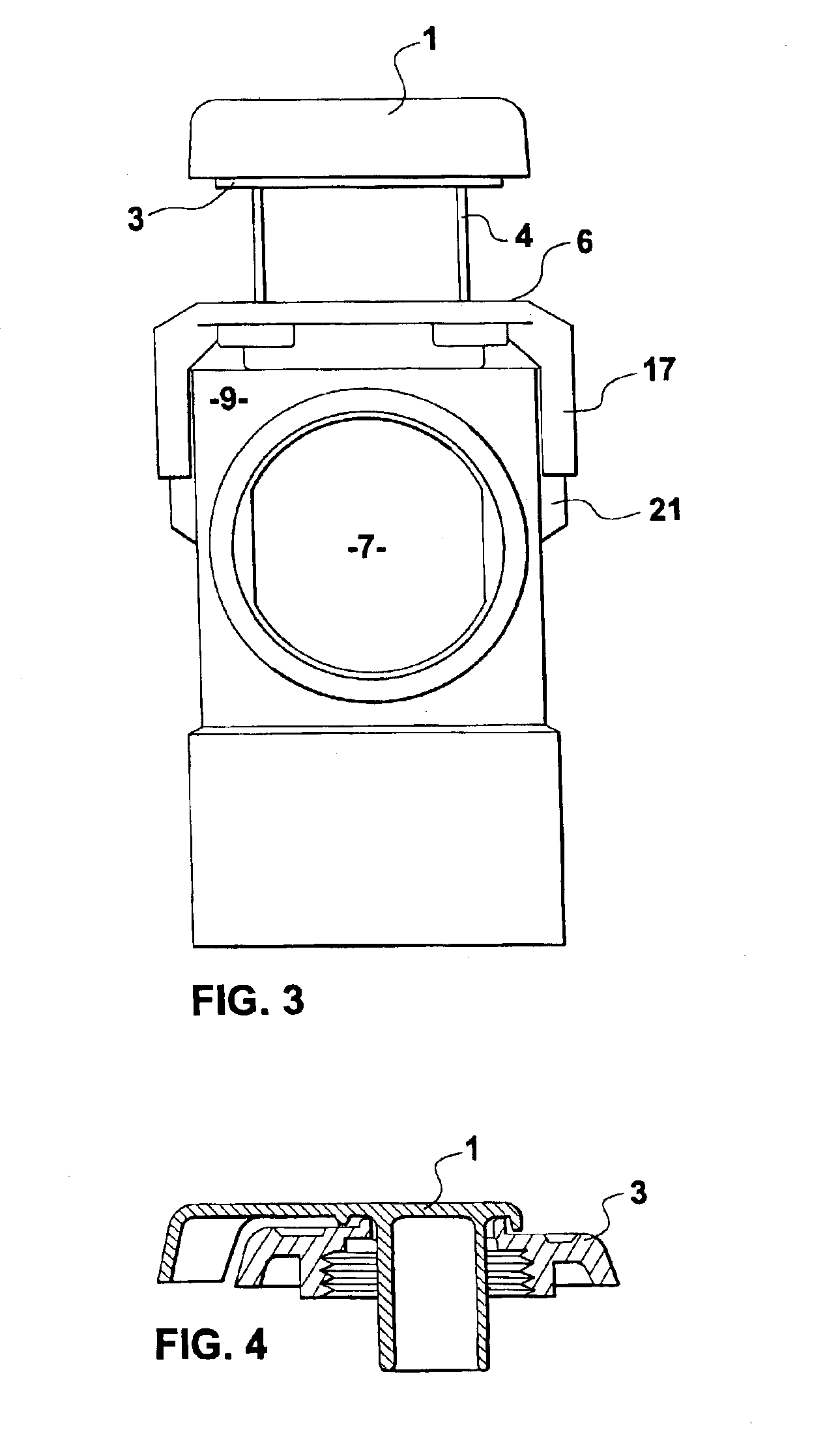
[0037]Referring to the drawings, a mounting assembly for an object such as a valve apparatus is shown. Throughout this description, and in the drawings, reference is made to a valve assembly which illustrates one example of an application of the mounting assembly provided by the invention.

[0038]In FIG. 1, the apparatus has an end cap 1 that is adapted to be manipulated by a user to operate a valve. The end cap is provided adjacent to an O-ring retainer 2 which retains O-rings 5. A front wall contacting member or front nut 3 is provided within the end cap and the front nut 3 has a thread that engages with a threaded outer surface of sleeve 4. A stem 12 is provided from the body or housing of the valve assembly that is to be mounted about the wall aperture 11 to the wall 10, and the sleeve 4 is free to rotate about stem 12. However, stem 12 has a slight recess within which a protruding part 14 of sleeve 4 is provided to prevent the sleeve from being removed from stem 12. The only way ...


PUM

PropertyMeasurementUnit
axial distanceaaaaaaaaaa
thicknessaaaaaaaaaa
distanceaaaaaaaaaa

Abstract

A mounting assembly is disclosed for mounting an object, such as a valve or a spa jet about an aperture in a wall such as a bath or shower wall. The assembly has the advantage that the object can be mounted such that it projects a predetermined distance from the front surface of the wall and can be secured to the wall by rotating a member on the front side of the wall. The invention also provides a valve assembly having relief between sealing surfaces to prevent the valve member seizing.

Description

FIELD OF THE INVENTION[0001]This invention relates to a mounting assembly and method for mounting apparatus, such as a valve assembly, in a wall, such as the wall of a bath or shower installation. The invention also relates to a valve assembly for use with a domestic water supply or a recirculating water supply such as a bath or shower installation.BACKGROUND OF THE INVENTION[0002]There are many instances where it is desirable to locate apparatus such as a spa jet or valve assembly, for example, in a wall of a bath or shower installation. In these applications it is desirable to have the apparatus project a constant distance from the front surface of the wall, independent of the thickness of the wall. One particular example of this occurs in various shower bath installations where the wall of the shower can vary in thickness from one installation to another. Often valve assemblies need to be mounted in such walls. These valve assemblies need to project a constant known distance from...

Claims


Application Information

Patent Timeline
Patent Type & Authority Patents(United States)
IPC IPC(8): A61H33/00
CPCA61H33/6063Y10T137/0402Y10T137/698
Inventor MARKS, KIPLEY ROYDON
Owner MARKS KIPLEY ROYDON
Why Eureka
Try Eureka