Venting seal for dispenser

a dispenser and sealing technology, applied in the field of dispensers, to achieve the effect of facilitating air flow

Active Publication Date: 2005-05-31
NORDSON CORP
View PDF23 Cites 36 Cited by
  • Summary
  • Abstract
  • Description
  • Claims
  • Application Information

AI Technical Summary

Benefits of technology

[0011]The filler push rod has a pusher body with a front end having a central projection thereon dimensioned to bear only upon the plug. The dispenser push rod used for the dispensing of the contents bears upon the body of the piston and does not effect deflection of the flange of the plug. Preferably, the body of the plug has a peripheral surface tapering to a reduced diameter at its rear end to facilitate air flow.

Problems solved by technology

If the vent is not completely closed, there are obvious problems when the syringe is put into use.
If the air is not completely evacuated, it may interfere with the operation of the dispenser by causing disruptions in a smooth flow.

Method used


Image

  • Venting seal for dispenser
  • Venting seal for dispenser
  • Venting seal for dispenser

Examples


Embodiment Construction

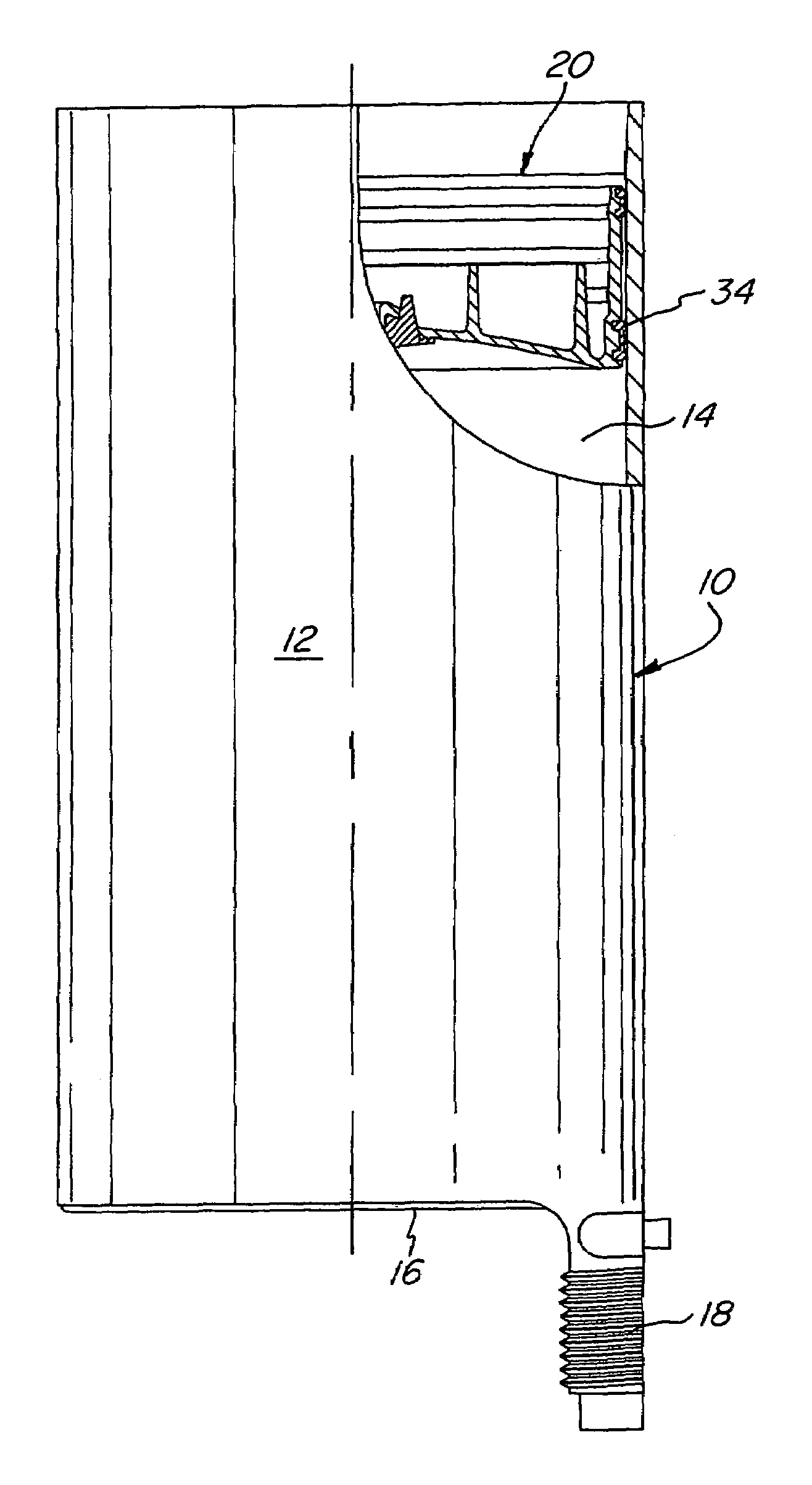
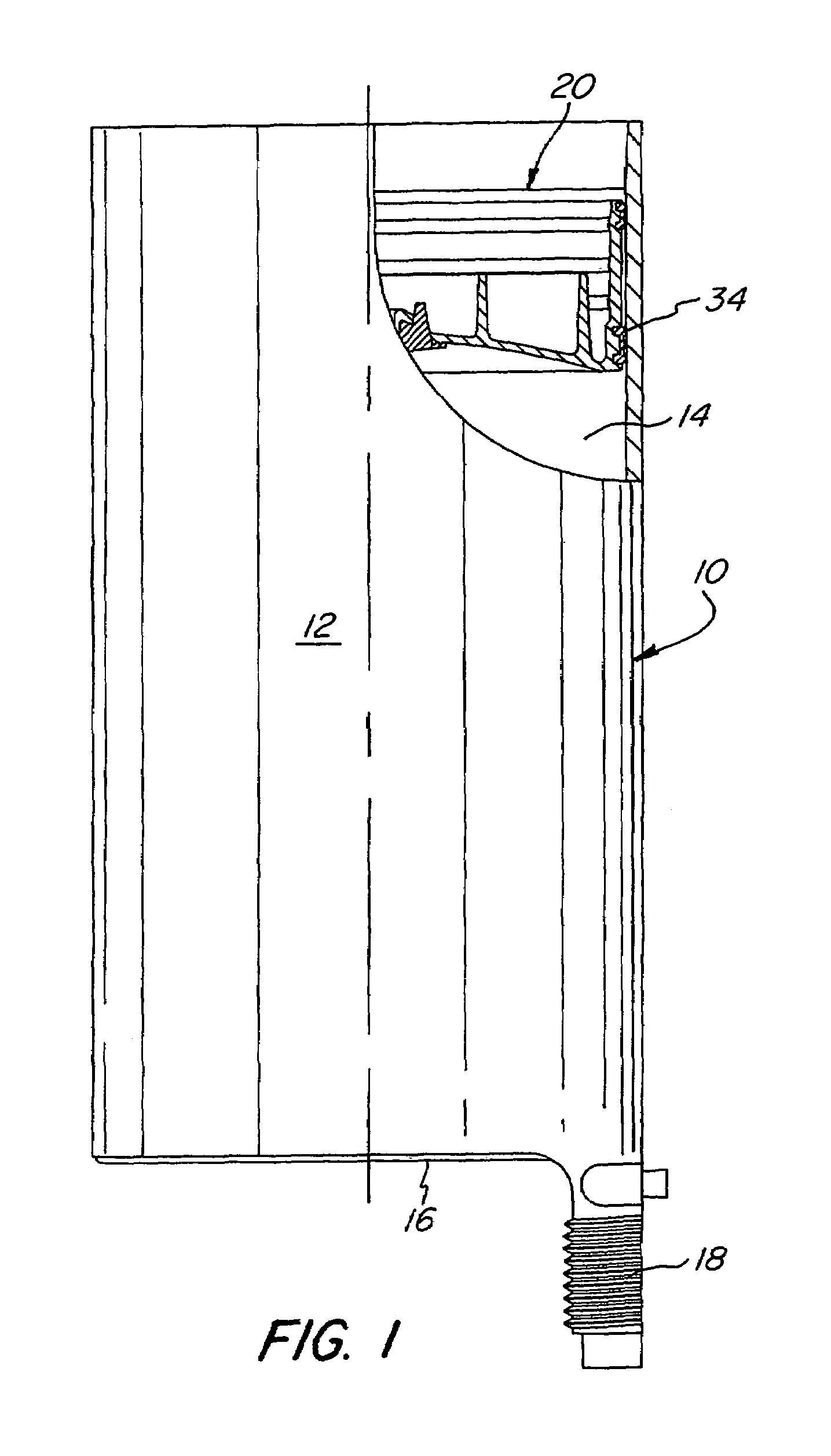
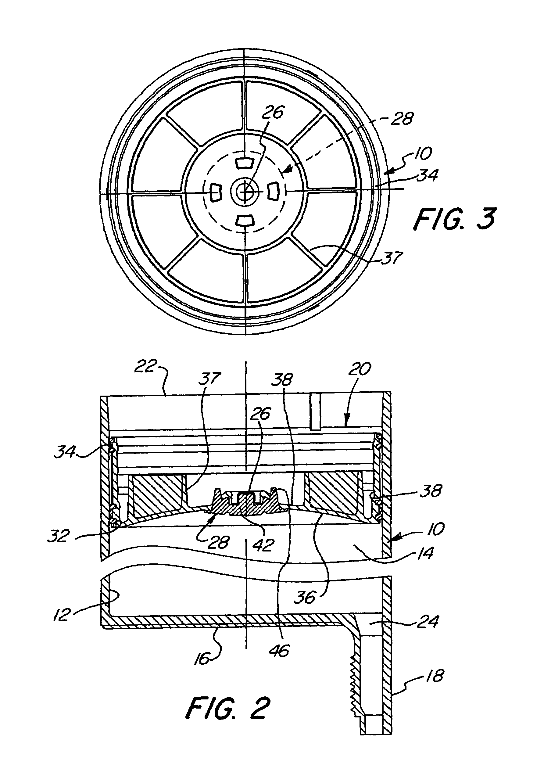
[0022]Turning first to FIGS. 1 and 2 of the attached drawings, therein illustrated is one barrel of a two barrel dispensing syringe comprising a generally cylindrical container generally designated by the numeral 10 having a peripheral wall 12 defining a cavity 14 therein, an end wall 16 with one-half of dispenser neck 18. Slidably seated within the cavity 14 is a piston generally designated by the numeral 20. Not shown is a conventional push rod which extends through the open end 22 of the container 10 to bear upon and push the piston 20 towards the end wall 16 and thereby dispense the material stored in the cavity 14 through a discharge opening 24 into the neck 18 upon which is threadably mounted a mixer / nozzle (not shown).

[0023]As seen in FIG. 2, the piston 20 is of circular cross section with a central orifice 26 in which is seated a plug generally designated by the numeral 28. The peripheral wall 30 of the piston 20 has two pairs of axially spaced grooves 32 formed therein and ...


PUM


Abstract

A dispenser includes a container providing a cavity and a discharge opening at one end. A piston in the cavity has a peripheral wall portion sealing against the inner wall of the container and a centrally disposed passage therethrough. A sealing plug of resiliently deformable material is seated in the passage and has a peripheral flange about the front end adjacent the discharge opening. The flange bears upon the surface of the front wall of the piston about the passage to effect a seal therebetween. A filler push rod bears upon the surface of the sealing plug is movable to move the flange of the plug away from the surface of the piston to allow air to vent through the passage about the periphery of the plug.

Description

BACKGROUND OF THE INVENTION[0001]The present invention relates to dispensing devices such as syringes and the like, and, more particularly to such a dispenser in which there is provided means for evacuating air from the cavity after product has been placed therein and the piston inserted thereabove.[0002]As is well known, syringes and like dispensers in which a plunger or push rod is pushed to dispense the contents are widely used for many applications from medicine to industrial activities. Generally, such dispensers will have a barrel or other container providing the cavity, a dispensing opening at one end, and the other end is open end for insertion of the product thereinto. Because it is desirable to avoid leakage around the piston as it is moved forward to dispense the material, air is trapped below the piston as it is pushed into the cavity above the material.[0003]In order to eliminate the air from the cavity, various procedures have been utilized including a vent in the pist...

Claims


Application Information

Patent Timeline
Patent Type & Authority Patents(United States)
IPC IPC(8): G01F11/00A61M5/31A61M5/315B01L3/02B65D83/00
CPCB65D83/0005A61M5/31511A61M2005/3123B65D2205/04B01L3/0206
Inventor SANDHOLM, ALBERT E.FREY, CHARLES M.
Owner NORDSON CORP
Why Eureka
Try Eureka