Fuel swirler plate for a fuel injector

a swirler plate and fuel injector technology, applied in the field of fuel swirler plates, can solve the problems of large fuel droplets, large diameters, and easy plugging of fuel and combustion deposits, and achieve the effects of improving atomization of fuel, high angular velocity, and high velocity

Inactive Publication Date: 2005-05-31
DELPHI TECH INC
View PDF16 Cites 28 Cited by
  • Summary
  • Abstract
  • Description
  • Claims
  • Application Information

AI Technical Summary

Benefits of technology

[0012]Briefly described, a fuel swirler plate for improving atomization of fuel in a fuel injector includes a plurality, preferably six, of identical fuel supply passages formed in the plate. Each passage includes an outer reservoir region wherein fuel is received from a source; an inwardly converging region having converging passage walls wherein fuel from the reservoir region is both accelerated and turned partially in a direction tangential to the axis of the plate and fuel injector; a metering cross-section formed as a minimum cross-sectional area in the converging region; and an exit region wherein the fuel dispensed from each passage combines with similar fuel flows from the other passages to form a high velocity swirl annulus between the swirler plate and a pintle ball of the fuel injector valve. The valve seat is conical below the ball, such that the swirl annulus, in descending the seat toward the exit from the fuel injector body, is further accelerated into a vortex having a very high angular velocity. Upon exiting the fuel injector, the fuel vortex spreads substantially instantaneously into a predictable, controlled hollow cone wherein the fuel may become vaporized before striking a surface. An advantage of the novel swirler plate over prior art plates is that, when the injector valve is closed, only a very small volume of fuel resides upstream of the valve seat in the annular region between the pintle ball and the exit region of the plate; and further, such residual fuel, which can cause large SAC sprays in prior art arrangements, is urged rotationally and becomes the leading edge of a new vortex each time the valve is opened, thus minimizing SAC spray formation.

Problems solved by technology

As the hole diameter decreases, the droplet size also decreases desirably at a given pressure; however, if the hole diameter is too small, the holes are susceptible to plugging from fuel and combustion deposits.
Therefore, a physical barrier (hole diameter) limits the minimum droplet size obtainable with a director style injector spray tip.
A disadvantage of prior art pressure-swirl atomizers is that large droplets of fuel, known in the art as a “SAC” spray, are released into the spray chamber at the beginning of each injection pulse.
These large droplets in the SAC spray are undesirable because the fuel contained therein is generally non-metered and can also reach chamber surfaces where it can produce carbon formation in fuel cells, as well as higher emissions from internal combustion engines.
Manufacturing costs associated with the use of powdered metal swirlers are relatively high.
However, such limitations restrict the performance of the part.
Additionally, this process can also result in sharp edges and abrupt transitions that can induce the flow to separate undesirably from the edges, resulting in cavitation erosion of the swirler and unpredictable flow patterns.
Slight variations in edges can translate into non-uniformity in the produced parts and resulting flow variations.

Method used


Image

  • Fuel swirler plate for a fuel injector
  • Fuel swirler plate for a fuel injector
  • Fuel swirler plate for a fuel injector

Examples


Embodiment Construction

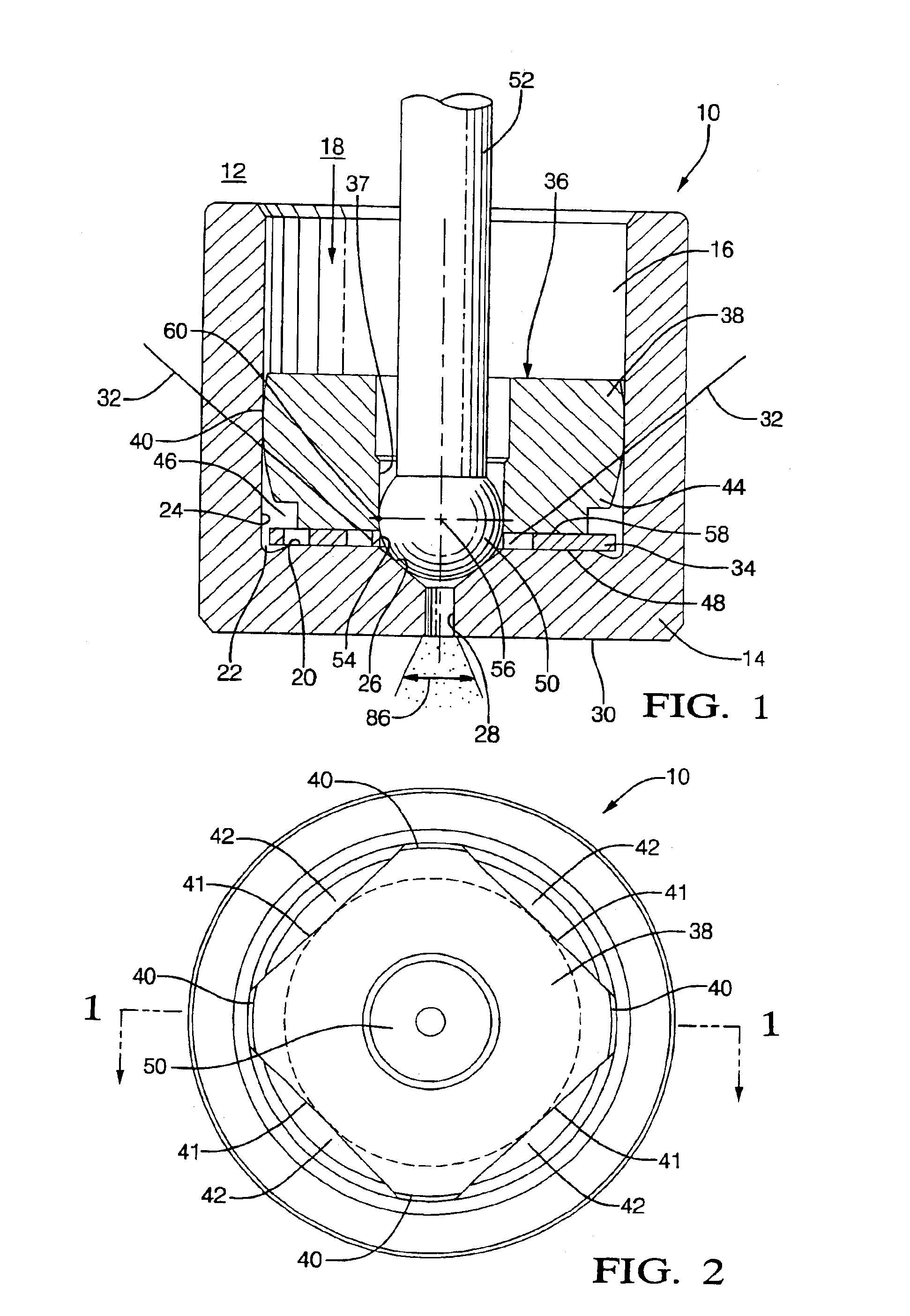
[0021]Referring now to the drawings, and particularly to FIGS. 1 and 2, nozzle 10 for incorporation into a fuel injector (shown schematically as 12) for an internal combustion gasoline or diesel engine, or a fuel reformer for a fuel cell (not shown). Nozzle 10 includes a nozzle body 14 having a bore 16 for receiving fuel 18 from a source in known fashion. Bore 16 terminates in a plate seat 20 which is preferably slightly undercut 22 at its juncture with bore wall 24. Coaxial with bore 16 and plate seat 20 is a frusto-conical valve seat 26 terminating in a cylindrical outlet passage 28 which opens axially through an end wall 30 of body 14. Valve seat 26 preferably has an included cone angle 32 of about 90°.

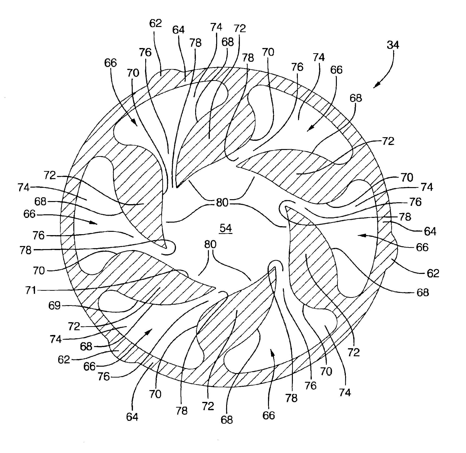
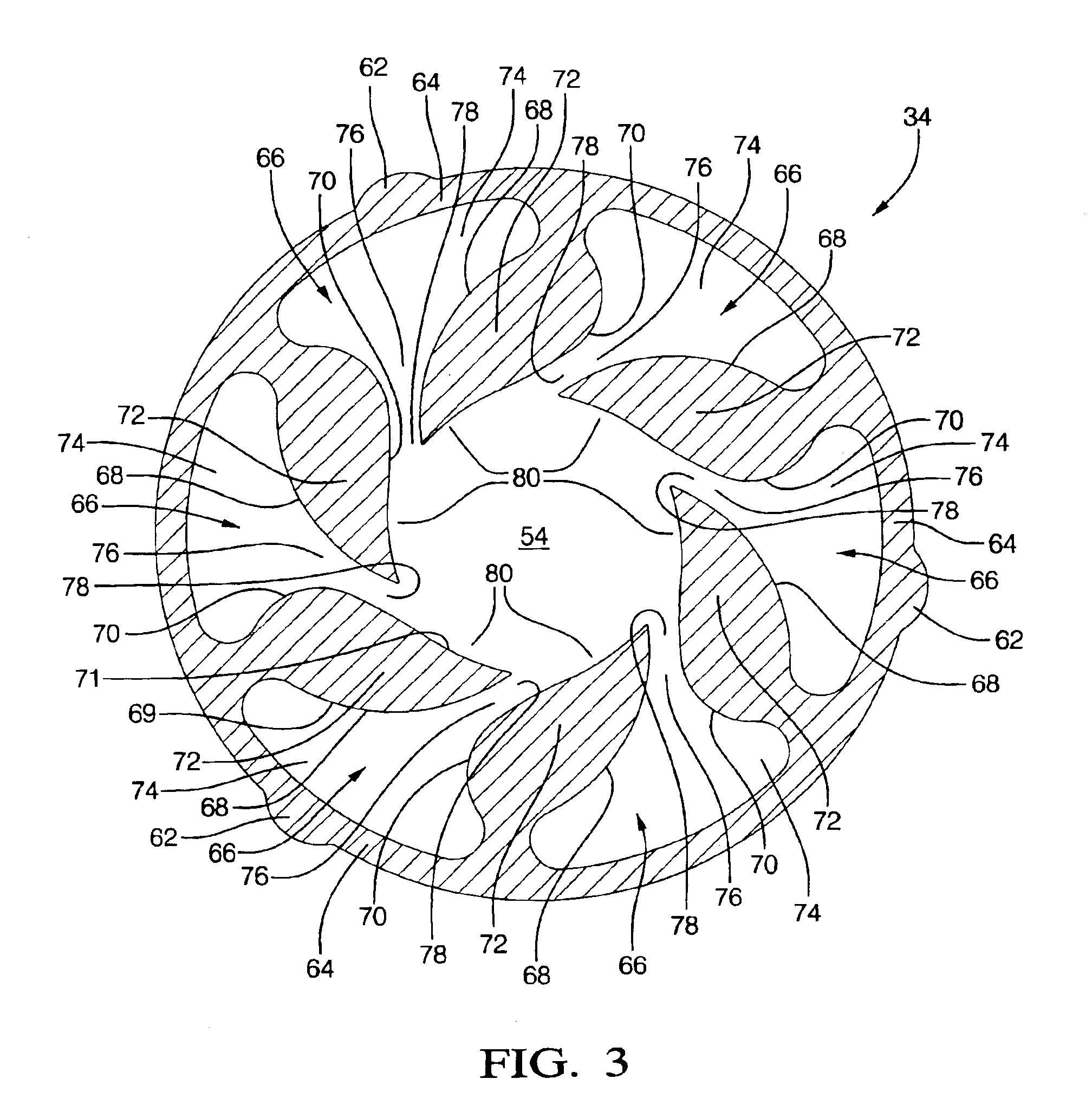
[0022]A flat pressure-swirl plate 34 in accordance with the invention is coaxially disposed on plate seat 20 and is retained thereupon by plate retainer 36 which is press-fit into bore 16 and itself has a central bore 37. The upper portion 38 of retainer 36 has a plurality of cylin...


PUM


Abstract

A fuel swirler plate for improving atomization of fuel in a fuel injector. A plurality of identical fuel supply passages is formed in the plate, each passage including an outer fuel reservoir region; a region having converging walls wherein fuel is accelerated and turned partially tangential to the axis of the plate and fuel injector; a metering region wherein flow is regulated; and an exit region wherein the fuel is combined with similar fuel flows from the other passages to form a high velocity swirl annulus between the swirler plate and a pintle ball of the fuel injector. An advantage of the novel swirl plate over prior art plates is that, when the injector valve is closed, only a very small volume of fuel resides in the swirl annulus between the pintle ball and the exit region of the plate, and such residual fuel is urged rotationally and becomes the leading edge of a new vortex the next time the valve is opened, thus minimizing SAC spray formation. The present invention is useful in fuel cells, burners, and in both direct injection and port injection fuel injectors of internal combustion engines.

Description

RELATIONSHIP TO OTHER APPLICATIONS[0001]The present application draws priority from a U.S. Provisional Application, Ser. No. 60 / 391,007, filed on Jun. 24, 2002.TECHNICAL FIELD[0002]The present invention relates generally to fuel injectors for injecting liquid fuel into internal combustion engines or fuel reformers; more particularly, to fuel injectors having pressure-swirl atomizers for providing a finely atomized fuel spray; and most particularly, to a pressure-swirl atomizer including a flat plate having converging swirler passages for providing an improved level of atomization.BACKGROUND OF INVENTION[0003]Fuel injectors are well known for supplying metered amounts of fuel to combustors such as internal combustion engines, and reformers such as hydrogen / reformate generators for fuel cells. In either case, it is highly desirable that the fuel spray created by these injectors be well atomized for essentially instantaneous vaporization upon entering the spray chamber, whether it be t...

Claims


Application Information

Patent Timeline
Patent Type & Authority Patents(United States)
IPC IPC(8): F02M61/00F02M61/16F02M61/18
CPCF02M61/162F02M61/188F02M61/18
Inventor VARBLE, DANIEL L.MIENEY, HARRY R.COOPER, RICHARD L.ROGERS, DAVIDALLEN, KEVIN J.
Owner DELPHI TECH INC
Why Eureka
Try Eureka