Closure device for vacuum closure of at least one opening in a wall

a technology of vacuum closure and opening, which is applied in the direction of valves, mechanical devices, pillows, etc., can solve the problems of significant pressure relative to the vacuum, risk of leakage, and risk of leakage in the piston-cylinder units which are accordingly located in the vacuum area, so as to reduce the risk of leakage, and facilitate service

Inactive Publication Date: 2005-05-31
VAT HLDG AG
View PDF9 Cites 109 Cited by
  • Summary
  • Abstract
  • Description
  • Claims
  • Application Information

AI Technical Summary

Benefits of technology

[0010]One object of the invention is to provide a closure device of the type mentioned in the beginning in which the risk of leakage is reduced. Another object of the invention is to provide a closure device which is easy to service while nevertheless reducing the risk of leakage. Another object of the invention is to provide a closure device of the type mentioned in the beginning which is suitable particularly for closing a plurality of slot-shaped openings. Another object of the invention is to provide a closure device of the type mentioned in the beginning in which there can be a vacuum area on both sides of the opening.
[0012]The removable cover makes it possible to install the piston in the cylinder bore hole of the carrier unit and also makes possible any subsequent servicing of this piston. The construction according to the invention substantially reduces the risk of a leak between the cover and the carrier unit. Also, the damage caused by a leak of this kind is substantially reduced.
[0013]In an advantageous embodiment form of the invention, the cover is provided on the side of the piston remote of the valve plate. The piston rod is guided out of the carrier unit through a bore hole in the latter and the piston rod is sealed relative to the carrier unit by means of at least two sealing rings arranged at the carrier unit, and a line which is connected with the atmosphere or can be evacuated leads into the space enclosed by these two sealing rings. In this way, the risk of a leak between the piston rod and the carrier unit is substantially reduced. It would also be conceivable and possible to arrange the cover on the side of the piston facing the valve plate. In this case, the piston rod can be guided out of the carrier unit through a bore hole in the cover. In this case, two sealing rings arranged at the walls of the bore hole in the cover can advantageously be provided for sealing between the cover and the piston rod, and a line which can be connected to the atmosphere or evacuated leads into the space enclosed by these two sealing rings.
[0014]In an advantageous embodiment form of the invention, it is further provided that the piston rod of the at least one piston-cylinder unit for displacing the at least one carrier unit relative to the cylinder housing out of which it is guided through a bore hole is sealed by means of at least two sealing rings arranged at the cylinder housing and a line which is connected with the atmosphere or can be evacuated leads into the space enclosed by these two sealing rings. This also substantially reduces the risk of leakage for these piston-cylinder units.

Problems solved by technology

When closure devices such as these which are described in U.S. Pat. No. 6,056,266 A and DE 196 33 798 A1 are to be used in applications in which there can be a vacuum on both sides of the opening in the wall, there is a considerable risk of leakage in the piston-cylinder units which are accordingly located in the vacuum area.
The risk of leakage is present especially because of the increased pressure of the compressed air acting upon the piston.
The resulting difference in pressure relative to the vacuum is substantially greater than the atmospheric pressure so that the risk of leakage is substantially higher.
The damage which could occur in case of leakage is also generally greater compared to a leak relative to the atmosphere, since the pressure in case of a leak in the vacuum chamber is considerably greater than the atmospheric pressure so that, for example, bending of the chamber walls or additional leaks, e.g., in the area of welds, can occur.
This device is disadvantageous particularly in that the bellows forming the cylinder spaces must be constructed so as to be very stable in order to absorb the pressure of the compressed air admitted into the cylinder space.
Also, there is a considerable risk of leakage in bellows of this kind particularly after an extended period of use and compressed air can escape into the vacuum chamber in case of leaks.
A further disadvantage in this valve device is that the closure plates can only be exchanged with difficulty.
However, it is necessary to exchange the closure plate occasionally particularly when aggressive process gases are used.
Also, the spaces encapsulated by the diaphragm bellows can only be accessed with difficulty.

Method used


Image

  • Closure device for vacuum closure of at least one opening in a wall
  • Closure device for vacuum closure of at least one opening in a wall
  • Closure device for vacuum closure of at least one opening in a wall

Examples


Embodiment Construction

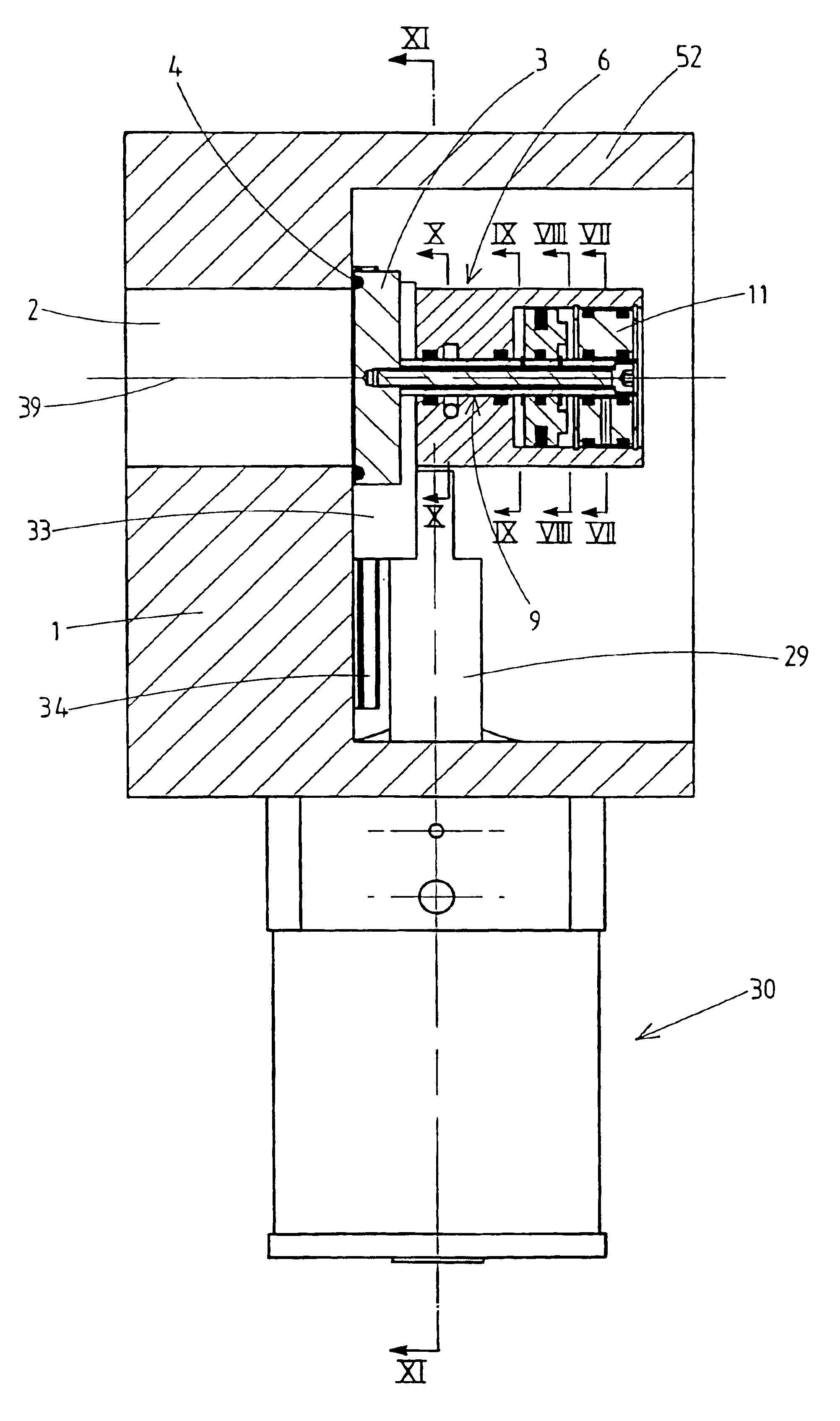
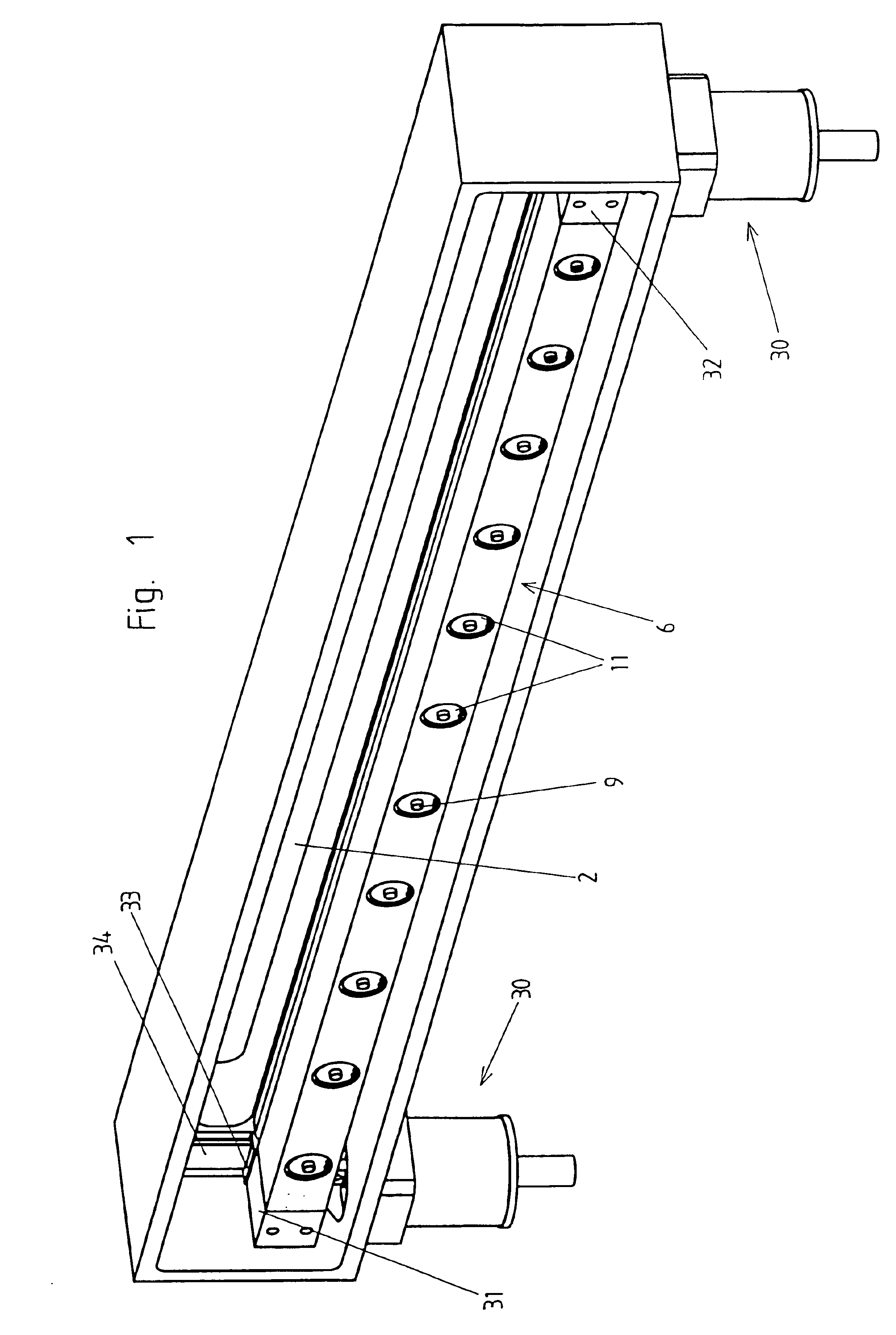
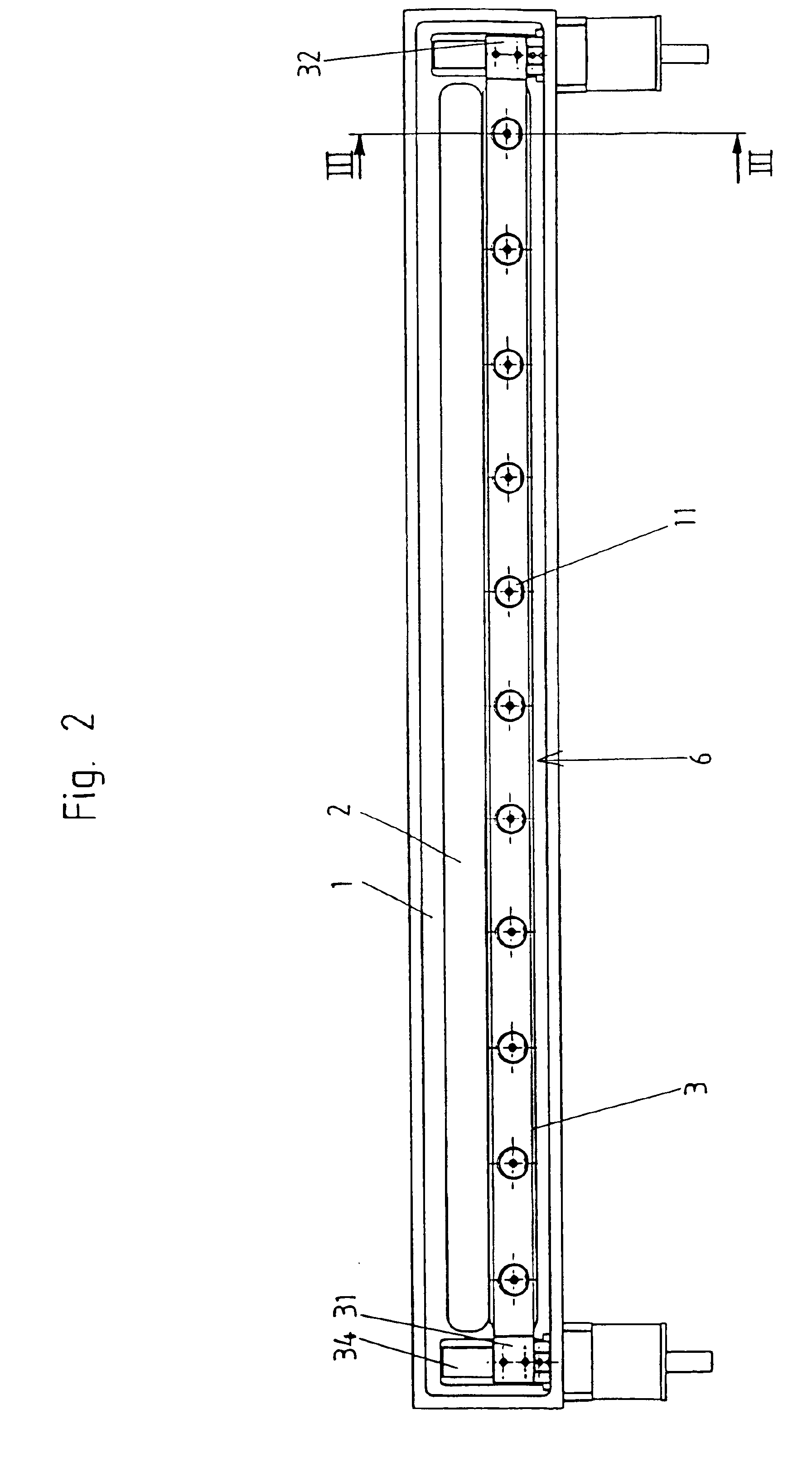
[0032]The embodiment example of a closure device according to the invention shown in FIGS. 1 to 11 serves for vacuum closure or vacuum sealing of an individual slot-shaped opening 2 in a wall 1. By the expression vacuum closure is meant herein that the opening 2 in the closed state of the closure device is closed in such a way that a vacuum can be maintained at least on one side of the wall (on the left-hand side of the wall with reference to FIG. 5). The closure device can also be constructed in such a way that it is stable with respect to differential pressure on both sides, i.e., a vacuum can be maintained on the left-hand side of the wall 1 with reference to FIG. 5 and there can be atmospheric pressure on the right-hand side with reference to FIG. 5 or, conversely, a vacuum can be maintained on the right-hand side of the wall with reference to FIG. 5 and there can be atmospheric pressure on the left-hand side with reference to FIG. 5. In the present context, a vacuum designates ...


PUM


Abstract

A closure device for a vacuum closure of at least one opening in a wall having a valve place, at least one piston-cylinder unit, at least one carrier unit, at least one cylinder bore hole, at least two sealing rings, and a line. The valve plate is associated with an opening and is displaceable between an open position in which it releases the opening, a position in which it covers the opening but is raised from the wall and a closed position in which it covers the opening and contacts the wall. The at least one piston-cylinder unit serves to displace the valve to the different positions and includes a pneumatically actuated piston. At least one carrier unit is connected to a piston rod which serves to displace the valve to the different positions.

Description

BACKGROUND OF THE INVENTION[0001]a) Field of the Invention[0002]The invention is directed to a closure device for vacuum closure of at least one opening in a wall, comprising a valve plate which is associated with a respective opening and which is displaceable between an open position in which it releases the opening, a position in which it covers the opening but is raised from the wall, and a closed position in which it covers the opening and contacts the wall, at least one piston-cylinder unit which serves to displace the valve plate between its open position and its position in which it covers the opening but is raised from the wall and which comprises a pneumatically actuated piston which is arranged in a cylinder housing and which is outfitted with a piston rod leading out of the cylinder housing through a bore hole, at least one carrier unit which is connected to the piston rod of the at least one piston-cylinder unit and which is associated with a respective valve plate, has ...

Claims


Application Information

Patent Timeline
Patent Type & Authority Patents(United States)
IPC IPC(8): F16K3/18F16K3/02F16K51/02F16K25/00F16K31/122
CPCF16K51/02F16K3/188A47G9/007A47G9/10
Inventor DUELLI, BERNHARD
Owner VAT HLDG AG
Why Eureka
Try Eureka