
Lawn mower adjustable wheel conversion assembly

a technology of conversion assembly and lawn mower, which is applied in the field of adjustable wheel conversion assembly, can solve the problems of uniform deficiency in providing, diminishing the effectiveness of the mower blade, and reducing the proximity of the rotating blade to stationary objects, so as to improve the maneuverability of the lawn mower

Inactive Publication Date: 2005-05-31
EAZY MOW
View PDF22 Cites 32 Cited by
  • Summary
  • Abstract
  • Description
  • Claims
  • Application Information

AI Technical Summary

Benefits of technology

[0011]As will be explained in greater detail further on in the specification, this arrangement is specifically designed to provide truly vertical adjustment for each wheel assembly along a longitudinal axis to effect the raising and lowering of the lawn mower as well as to provide the enhanced maneuvering of the lawn mower both around and in close proximity to stationary obstacles.

Problems solved by technology

While all of the aforementioned prior art constructions are more than adequate for the basic purpose and function for which they have been specifically designed, they are uniformly deficient with respect to their failure to provide a simple, efficient, and practical adjustable height wheel assembly that is quickly and easily adjusted in the vertical plane while still providing a 360 degree arc of rotation of the wheel castors.
As anyone who has employed the prior art devices is all too well aware, not only are their height adjustments not conducted in a linear vertical plane, but they also tend to extend outwardly from the mower housing thereby diminishing the effectiveness of the mower blade by diminishing the proximity of the rotating blade to stationary objects such as trees and fence lines.
In addition, the prior art constructions also have a tendency to restrict the maneuverability of the lawn mowers to which they are attached by hindering the rotation of the lawn mower in a 360 degree arc relative to a selected one of the lawnmower wheels.

Method used


Image

  • Lawn mower adjustable wheel conversion assembly
  • Lawn mower adjustable wheel conversion assembly
  • Lawn mower adjustable wheel conversion assembly

Examples


Embodiment Construction

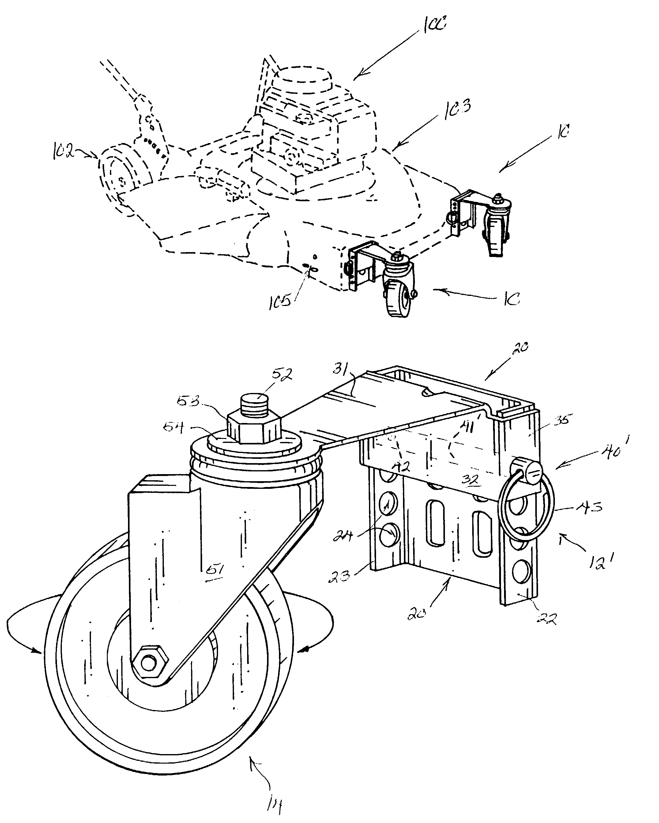
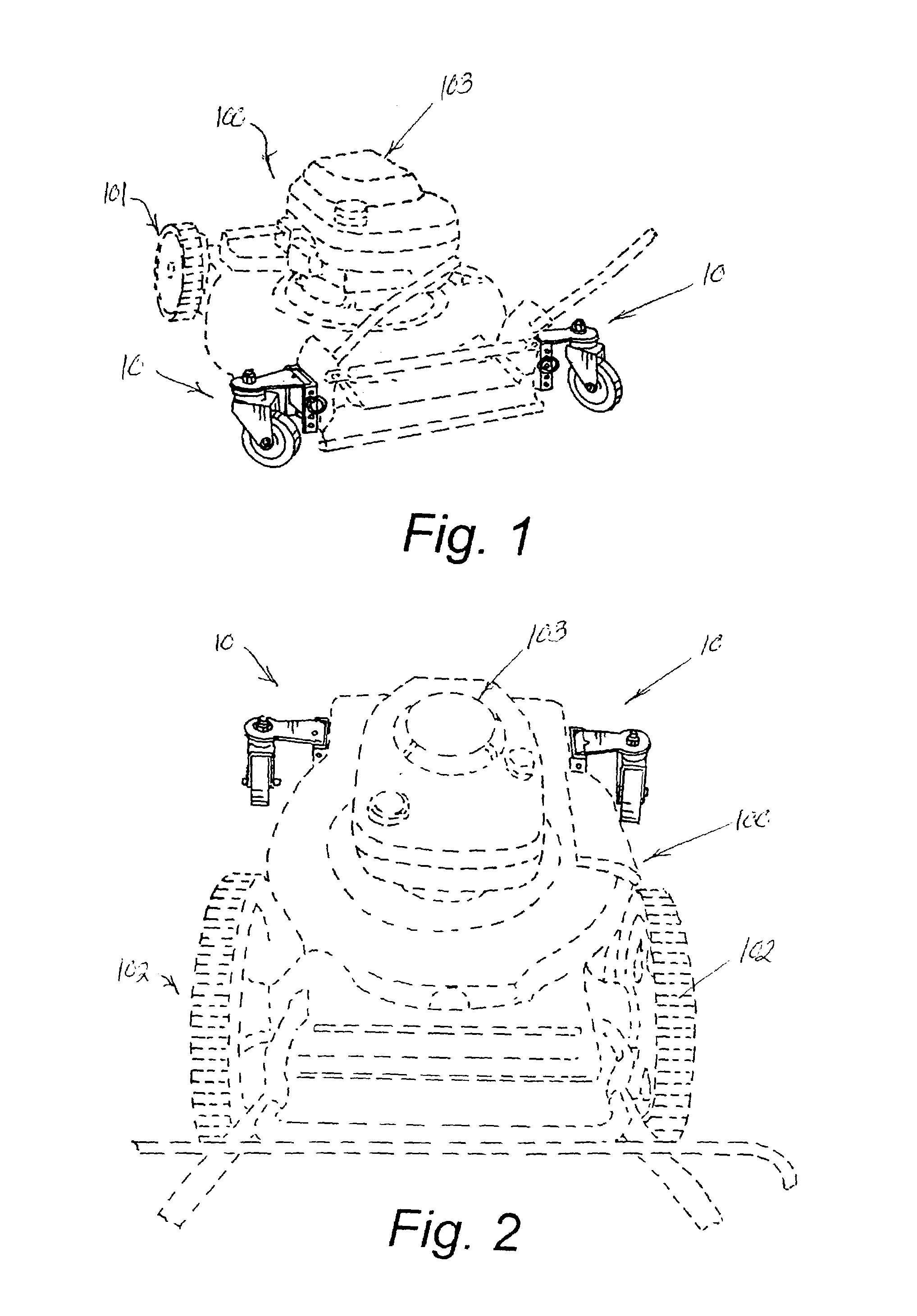
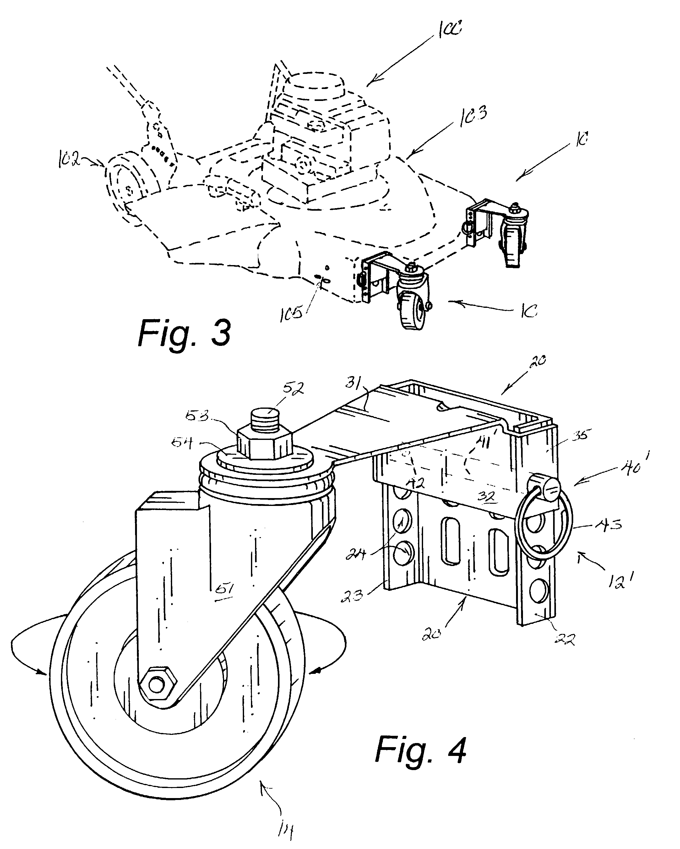
[0028]As can be seen by reference to the drawings, and in particular to FIGS. 1 through 3, the alternate version of the preferred embodiment of the vertically adjustable wheel assemblies that forms a portion of the basis of the present invention is designated generally by the reference number 10, depicted at various installation locations on a conventional lawn mower designated generally as 100 and having standard front wheel assemblies 101 and 101 and standard rear wheel assemblies 102102 that support the main lawn mower housing 103.

[0029]Turning now to FIGS. 4 and 5, it can be seen that each of the adjustable height wheel assemblies 10 comprises in general a mounting plate unit 11, an adjustment arm unit 12, a securing unit 13 and a wheel castor unit 14. These units will now be described in seriatim fashion.

[0030]As can best be seen by reference to FIG. 5, the mounting plate unit 11 comprises a generally U-shaped mounting plate member 20 including an enlarged generally rectangular...


PUM


Abstract

A pair of substitute adjustable height wheel assemblies 10 10 to replace either the front 101 and / or rear 102 wheel assemblies on a conventional lawn mower 100 wherein each adjustable height wheel assembly 10 includes a contoured mounting plate member 20 having a central portion 21 adapted to be secured at a desired location on the lawn mower housing 103 and including a pair of outwardly projecting leg portions 22 23 having a plurality of vertically spaced aligned apertures 24 dimensioned to selectively receive a securing unit 12 for positioning an adjustment arm unit 13 bearing a castor wheel unit 14 at a desired height relative to the mounting plate member 20 that is selectively positioned on the lawn mower (100).

Description

CROSS REFERENCE TO RELATED APPLICATIONS[0001]Not applicable.BACKGROUND OF THE INVENTION[0002]1. Field of the Invention[0003]The present invention relates to the field of adjustable wheel assemblies in general and in particular to a truly vertical adjustable wheel conversion assembly specifically designed for use with an adjustable height lawn mower.[0004]2. Description of Related Art[0005]As can be seen by reference to the following U.S. Pat. Nos. 3,649,828; 3,428,328; 3,421,776; 3,147,987; and, 3,038,736, the prior art is replete with myriad and diverse adjustable height wheel assemblies for lawn mowers.[0006]While all of the aforementioned prior art constructions are more than adequate for the basic purpose and function for which they have been specifically designed, they are uniformly deficient with respect to their failure to provide a simple, efficient, and practical adjustable height wheel assembly that is quickly and easily adjusted in the vertical plane while still providing...

Claims


Application Information

Patent Timeline
IPC IPC(8): A01D34/74A01D34/63B60B33/00
CPCA01D34/74B60B33/0002B60B33/0005B60B33/0007B60B33/0015B60B33/0021B60B33/0049B60B33/0057B60B33/0068B60B33/0073B60B33/04B60B33/0039Y10T16/182
Inventor BEARDEN, JOHN D.
Owner EAZY MOW
Learn More