Fiber optic plug and receptacle assembly

a technology of fiber optic plugs and receptacles, applied in the field of assembly, can solve the problems of fiber optic cable being subjected to torque-generating forces, fiber optic cable being disadvantageously increased, and the mechanical coupling between the fiber optic connector and the adapter sleeve limiting the float between the plug ferrule and the adapter sleev

Inactive Publication Date: 2005-05-31
CORNING OPTICAL COMM LLC
View PDF16 Cites 264 Cited by
  • Summary
  • Abstract
  • Description
  • Claims
  • Application Information

AI Technical Summary

Benefits of technology

[0013]According to an embodiment, a fiber optic assembly is also provided in which a fiber optic receptacle is designed to mate with a fiber optic plug. The fiber optic receptacle includes a fiber optic receptacle housing defining an internal cavity opening through opposed first and second ends. The fiber optic receptacle also includes an adapter sleeve disposed within the internal cavity defined by the receptacle housing. The adapter sleeve defines a lengthwise extending passage for receiving a portion of the plug ferrule of the fiber optic plug. In this regard, the plug ferrule is disposed within the plug body such that the plug ferrule is accessible within the shroud via the first end of the plug body, even though the shroud preferably extends somewhat beyond the plug ferrule. Further, the shroud and the adapter sleeve are sized such that portions of the adapter sleeve are disposed within the openings defined by the shroud once the plug ferrule of the fiber optic plug is inserted into the adapter sleeve. Thus, in this embodiment the shroud does not completely surround the adapter sleeve as provided by conventional fiber optic plugs. Accordingly, the shroud can be reduced in size relative to the shrouds of conventional fiber optic plugs, thereby decreasing the overall size of the fiber optic plug in this embodiment of this invention. Since the fiber optic plug sometimes limits the size of a duct or other passageway through which the fiber optic plug and the associated fiber optic cable are pulled, the fiber optic plug of this embodiment can advantageously be pulled through smaller ducts and other passageways than conventional fiber optic plugs.
[0016]In an embodiment, the fiber optic connector includes a spring push attached to the connector housing. In this embodiment, the first end of the crimp band engages the spring push. More particularly, the spring push may include a crimp body designed to be engaged by the first portion of the crimp band. With respect to the engagement of the fiber optic cable by the crimp band, the fiber optic cable may further include a support tube disposed within the cable jacket of the fiber optic cable and surrounding the plurality of optical fibers. The support tube is aligned with the second portion of the crimp band such that the second portion of the crimp band crimps the cable jacket between the second portion of the crimp band and the support tube. Thus, the crimp band securely engages both the fiber optic cable and the fiber optic connector. Moreover, the respective engagement members of the crimp band and the plug body may mechanically couple the crimp band and the plug body and prevent relative rotation therebetween, thereby protecting the fiber optic connector and, in turn, the plug ferrule from the otherwise deleterious effects of torque imparted upon the fiber optic cable.

Problems solved by technology

While the latches effectively couple the plug ferrule and the adapter sleeve, the mechanical coupling of the fiber optic connector and the adapter sleeve disadvantageously limit float between the plug ferrule and the adapter sleeve.
Once the plug and the receptacle have been mated, the fiber optic cable may be subjected to forces that create torque upon the fiber optic connector including the plug ferrule.
This torque will disadvantageously increase the attenuation of the optical signals transmitted via the optical fibers upon which the plug ferrule is mounted.
Even worse, this torque may break the optical fiber.
Since the plug body must be sufficiently large to receive and surround one end of the adapter sleeve, the size of the plug body may limit the minimum size of the duct or other passageway through which the fiber optic cable is installed.
This limitation on the minimum size of the duct is becoming increasingly disadvantageous as additional emphasis is now placed upon reducing the space required for installing a fiber optic cable, i.e., reducing the duct size, in view of the large number of fiber optic cables that are currently installed.
To date, however, reductions in the size of the duct through which a fiber optic cable is pulled are limited, at least in part, by the size of the plug body mounted upon the end portion of the fiber optic cable.

Method used


Image

  • Fiber optic plug and receptacle assembly
  • Fiber optic plug and receptacle assembly
  • Fiber optic plug and receptacle assembly

Examples


Embodiment Construction

[0032]This invention now will be described more fully hereinafter with reference to the accompanying drawings, in which preferred embodiments of the invention are shown. This invention may, however, be embodied in many different forms and should not be construed as limited to the embodiments set forth herein; rather, these embodiments are provided so that this disclosure will be thorough and complete, and will fully convey the scope of the invention to those skilled in the art. Like numbers refer to like elements throughout.

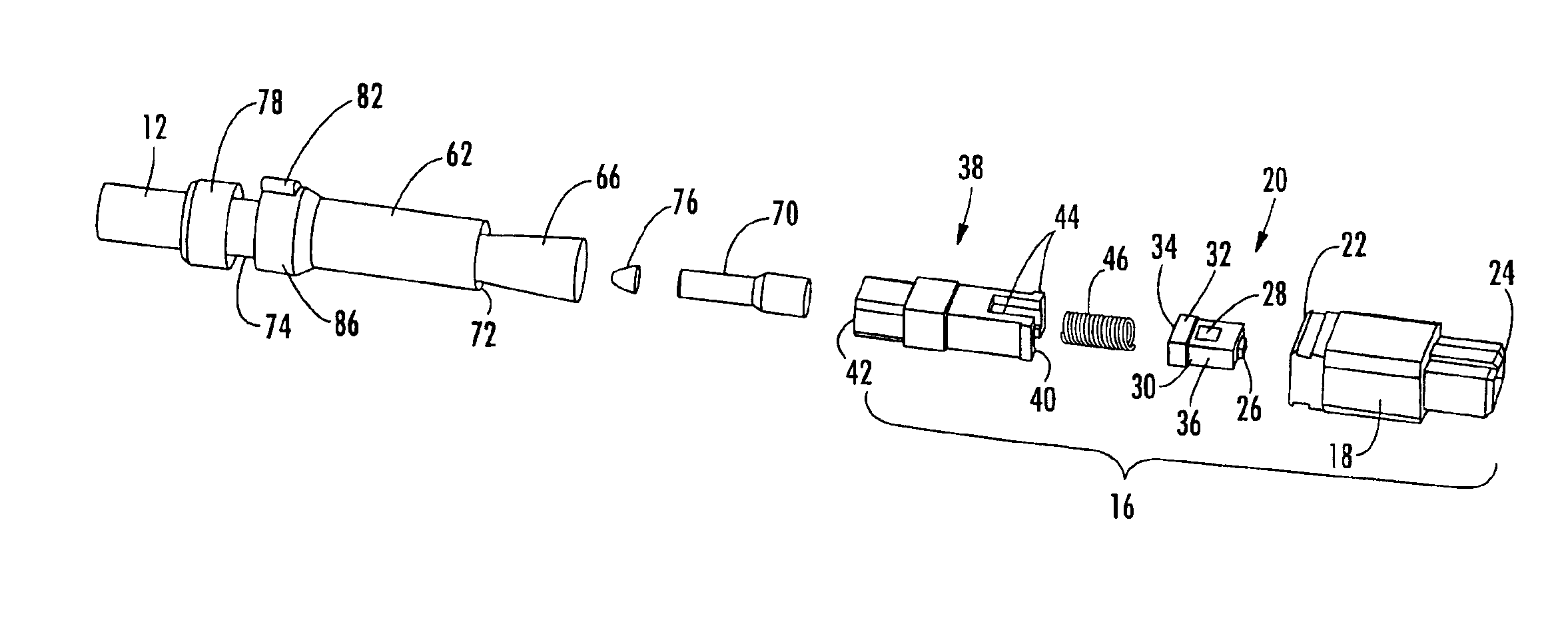
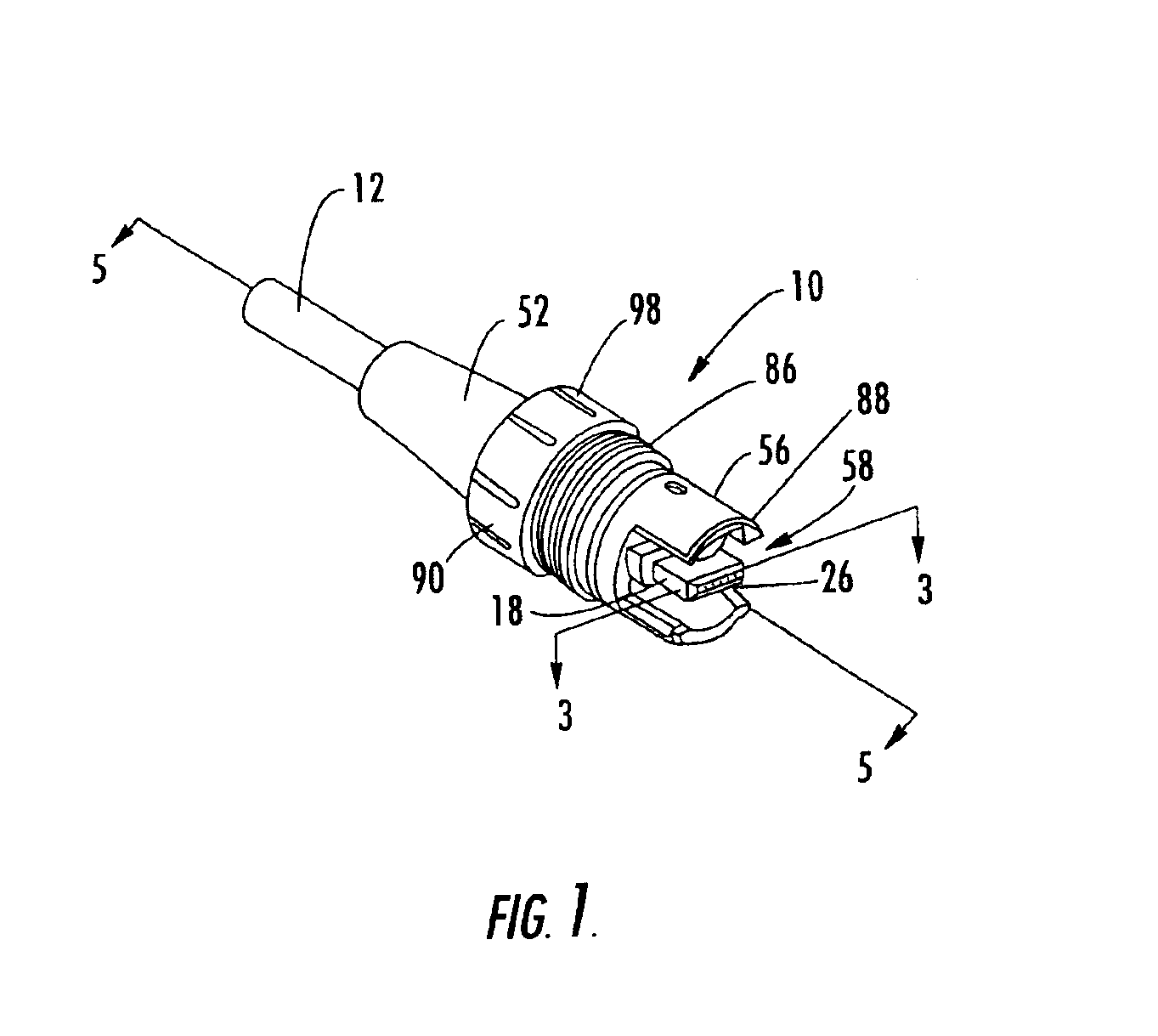
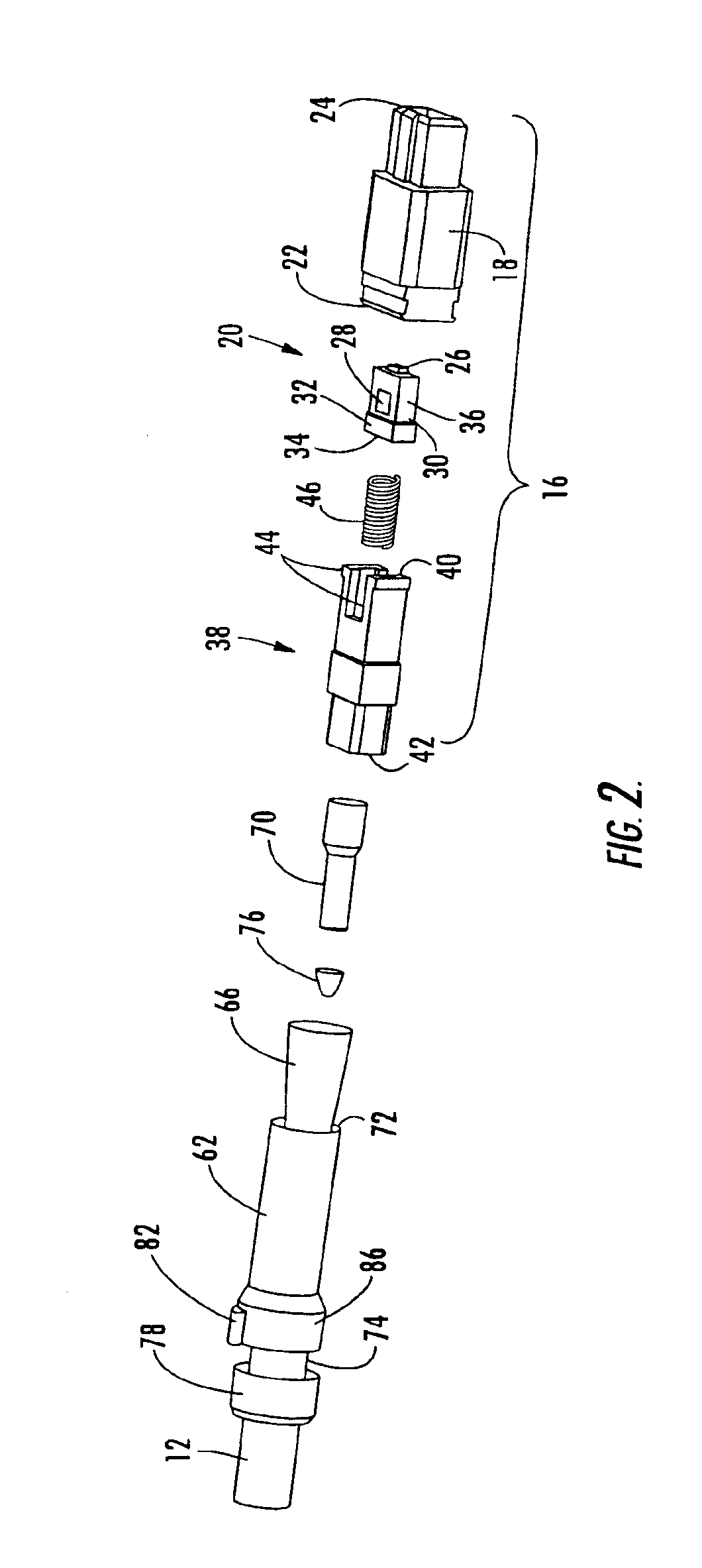
[0033]Referring to FIG. 1, a fiber optic plug 10 according to one embodiment of this invention is depicted. The fiber optic plug is mounted upon the end portion of a fiber optic cable 12 and is adapted to mate with a corresponding fiber optic receptacle. Typically, the receptacle provides access to an enclosure or the like such that the optical fibers (not shown) extending from the fiber optic cable may be aligned with and optically interconnected with optical fi...


PUM


Abstract

A relatively small fiber optic plug is provided to facilitate pulling of the fiber optic plug and an associated fiber optic cable through small passageways. The fiber optic plug may include a shroud that protects the fiber optic connector and that may further define at least one opening, and preferably a pair of openings. The openings are sized to receive portions of an adapter sleeve once the fiber optic plug is mated with a fiber optic receptacle. The fiber optic plug may also include a cap mounted upon and adapted to swivel relative to the remainder of the fiber optic plug to serve as a pulling grip during installation of the fiber optic cable. Further, the fiber optic plug may include a crimp band that is mechanically coupled to both the fiber optic cable and the plug body in order to isolate the fiber optic connector from torque otherwise created by forces to which the fiber optic cable is subjected.

Description

[0001]This application is a divisional of U.S. patent application Ser. No. 09 / 967,259 filed Sep. 28, 2001, now U.S. Pat. No. 6,648,520.FIELD OF THE INVENTION[0002]This invention relates generally to assemblies for interconnecting or otherwise terminating optical fibers and, more particularly, to fiber optic plugs for mating with corresponding receptacles.BACKGROUND OF THE INVENTION[0003]Optical fibers are used in an increasing number and variety of applications, such as a wide variety of telecommunications and data transmission applications. As a result, fiber optic networks must include an ever increasing number of enclosures in which one or more of the optical fibers are interconnected or otherwise terminated. For example, fiber optic networks, such as cable television (CATV) networks, may include a number of optical network units (ONUs) in which the optical signals propagating along the optical fibers are converted to respective electrical signals. In addition, telephone and CATV...

Claims


Application Information

Patent Timeline
Patent Type & Authority Patents(United States)
IPC IPC(8): G02B6/38G02B6/44
CPCG02B6/3869G02B6/4465G02B6/3887G02B6/3894G02B6/3897G02B6/3821G02B6/3849G02B6/3885G02B6/3888G02B6/545G02B6/36
Inventor MCDONALD, A. JOHNMELTON, STUART R.TRAN, HIEU V.LUTHER, JAMES P.CHILDERS, DARRELL R.
Owner CORNING OPTICAL COMM LLC
Why Eureka
Try Eureka