Electrical connector having a holddown for ground connection

a technology of ground connection and electric connector, which is applied in the direction of connection contact member material, coupling device connection, coupling protective earth/shielding arrangement, etc., can solve the problems of significant reduction in rigidity of insulation made of resin material and having a thin flat-plate shape, impaired flatness in arrangement of terminal portions of contacts, and failure to conn

Inactive Publication Date: 2005-05-31
JAPAN AVIATION ELECTRONICS IND LTD
View PDF8 Cites 12 Cited by
  • Summary
  • Abstract
  • Description
  • Claims
  • Application Information

AI Technical Summary

Benefits of technology

[0015]It is an object of this invention to provide an electrical connector in which a contact is reliably soldered to a ground

Problems solved by technology

In particular, the insulator made of a resin material and having a thin flat-plate shape is significantly decreased in rigidity if a reflow temperature for soldering is high.
In case where the insulator is pressed by the pressing spring portions and largely deformed, the flatness in arrangement of the terminal portions of the contacts is impaired.
Th

Method used


Image

  • Electrical connector having a holddown for ground connection
  • Electrical connector having a holddown for ground connection
  • Electrical connector having a holddown for ground connection

Examples


Embodiment Construction

[0030]Now, description will be made of an electrical connector according to an embodiment of this invention.

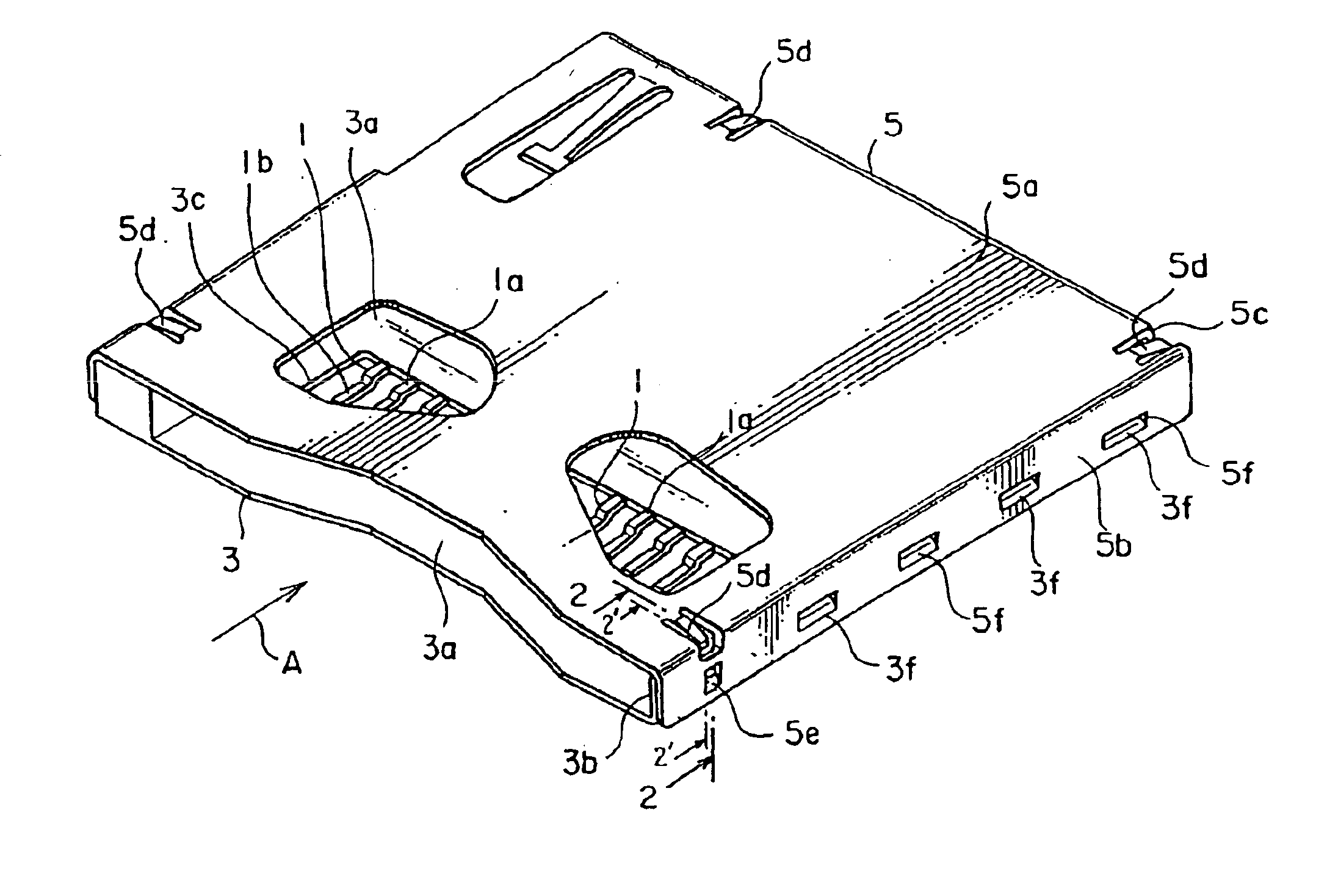
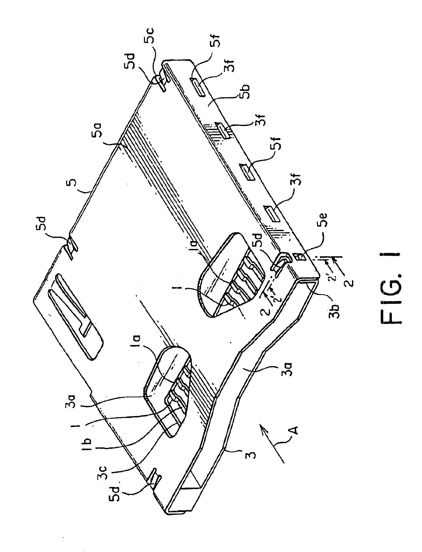
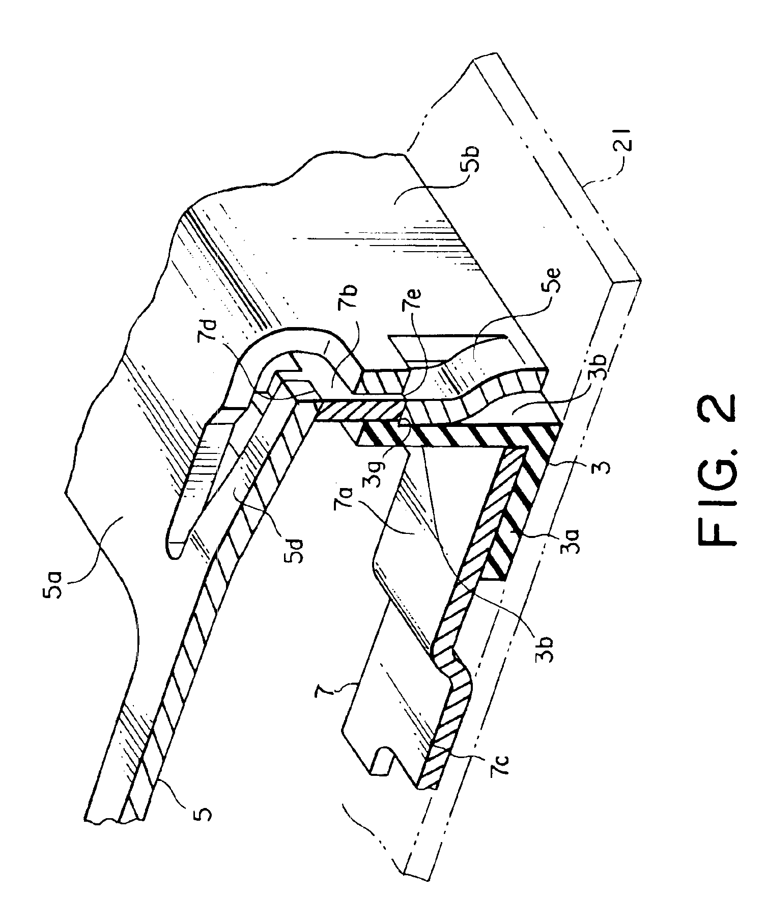
[0031]Referring to FIGS. 1 through 3, the electrical connector comprises a plurality of conductive contacts 1 arranged in parallel to one another with a space left from one another, an insulator 3 holding the contacts 1, a cover member 5 integrally attached to the insulator 3, and a plurality of conductive holddowns 7 held by the insulator 3.

[0032]Each of the contacts 1 has a contact point portion 1a to be contacted with a card contact point portion of a card (not shown), and a terminal portion 1b extending outward from the insulator 3. The terminal portion 1b is connected to a signal conductor portion (not shown) of a substrate 21 by soldering.

[0033]The insulator 3 is mounted on the substrate 21, such as a printed circuit board. The insulator 3 has a thin-plate base portion 3a holding the contacts 1, and a pair of thin-plate side wall portions 3b extending from opposite sides...


PUM


Abstract

An electrical connector comprises an insulator to be mounted to a substrate, a conductive cover member coupled to the insulator, and a conductive holddown held by the insulator to connect the cover member and a ground conductor portion formed on the substrate. The cover member has first and second cover contacting portions. The holddown has a holddown contacting portion extending to face an outer surface of a side wall portion of the insulator. The holddown contacting portion is clamped between the first and the second cover contacting portions in a direction along the outer surface of the side wall portion.

Description

[0001]This application claims priority to prior Japanese application JP 2003-48660, the disclosure of which is incorporated herein by reference.BACKGROUND OF THE INVENTION[0002]This invention relates to an electrical connector adapted to receive a thin card, such as an IC card, which is inserted into the electrical connector to be connected thereto.[0003]An existing electrical connector of the type comprises a plurality of conductive contacts, an insulator holding the contacts, a conductive cover member attached to the insulator, and a plurality of conductive holddowns held by the insulator.[0004]The insulator is adapted to be mounted on a printed circuit board. The insulator has a base portion and a pair of side wall portions standing up from the base portion. Each of the base portion and the side wall portions of the insulator has a thin flat-plate shape.[0005]The cover member has a cover main plate portion having a flat plate shape and faced to the base portion of the insulator, ...

Claims


Application Information

Patent Timeline
IPC IPC(8): H01R13/658H01R12/70H01R13/648H01R13/6582H01R24/00H01R107/00
CPCH01R12/707H01R13/65802H01R13/6582H01R13/648
Inventor KODERA, MASAFUMIMOTOJIMA, JOENATORI, AKIRASUZUKI, KEIICHIRO
Owner JAPAN AVIATION ELECTRONICS IND LTD
Why Eureka
Try Eureka