Drive control system for sensor-less motor

a sensorless motor and control system technology, applied in the direction of motor/generator/converter stopper, electronic commutator control, dynamo-electric converter control, etc., can solve the problem that the detection of rotation with the back electromotive force cannot be utilized during the transitional condition, the estimated operation cannot always be achieved, and the fault is generated at the beginning of the drive with a certain probability, etc. problem, to achieve the effect of accurate and rapid realization

Inactive Publication Date: 2005-05-31
RENESAS SEMICON PACKAGE & TEST SOLUTIONS
View PDF21 Cites 44 Cited by
  • Summary
  • Abstract
  • Description
  • Claims
  • Application Information

AI Technical Summary

Benefits of technology

[0011]Loss of synchronization (step-out) due to the unlock of PLL is also generated in some cases when the PWM duty becomes 100% due to reduction of voltage and over-load condition. A spindle motor is subjected to the soft-switch drive or sine-wave drive for smoothly changing over the power feeding phase. In this case, when the PWM duty reaches 100%, a current of the non-power feeding phase cannot be perfectly reduced to zero at the timing near the timing for detecting zero-cross of B-EMF and thereby a kick-back is generated in the drive voltage. Therefore, when the rotating position of rotor is detected with the zero-cross phase of B-EMF, such kick-back prevents accurate detection of the zero-cross phase and thereby such detection error becomes large and PLL is unlocked.
[0019]The present invention discloses a drive control system for sensor-less motor in which the motor is driven to rotate by switching a current of a field coil in each phase of a multi-phase sensor-less motor depending on the rotation phase of motor and the drive control thereof is subjected to the PLL control. Moreover, immediately after the drive of motor, a desired phase is selected as the detection phase, a voltage induced on the coil of the detection phase when the power is fed only for a short period of time to the field coil in the phase other than the detection phase and the magnetic pole position of rotor is detected from the amplitude condition of the induced voltage detected. Based on this detection, the power feeding phase of motor drive is determined and the power feeding to drive the motor is conducted depending on such determination. The detection of magnetic pole position and the power feeding to drive the motor are conducted alternately. Accordingly, drive of sensor-less motor can be realized accurately and quickly.

Problems solved by technology

In other words, in the drive control of a sensor-less motor explained above, the drive control in the steady rotating condition can be realized rather easily with the commutation and PLL controls based on the back electromotive force of field coil, but detection of rotation with the back electromotive force cannot be utilized during the transitional condition until the steady rotating condition is started, particularly immediately after the drive.
However, since the open loop control is a kind of estimated control method and the estimated operation cannot always be attained.
In the prior art, it has been inevitable that a fault is generated at the beginning of drive with a certain probability.
In the sensor-less motor not including a rotation sensor, if a drive mistake occurs, it is difficult to accurately detect such mistake.
A drive mistake occurs when the estimated operations are not carried out with a certain reason.
Therefore, if a drive error occurs, detection of such drive mistake is not executed as estimated with a considerable probability.
In this case, various problems such that recovery from the drive error and re-drive are delayed or the motor is stacked in the non-driven condition may be generated.
Moreover, a problem that shift to the steady operation from drive is not carried out smoothly and the sequence to shift to the drive control of steady operation is executed even when the drive fails has been generated easily.

Method used


Image

  • Drive control system for sensor-less motor
  • Drive control system for sensor-less motor
  • Drive control system for sensor-less motor

Examples


Embodiment Construction

[0032]The preferred embodiments of the present invention will be explained with reference to the accompanying drawings.

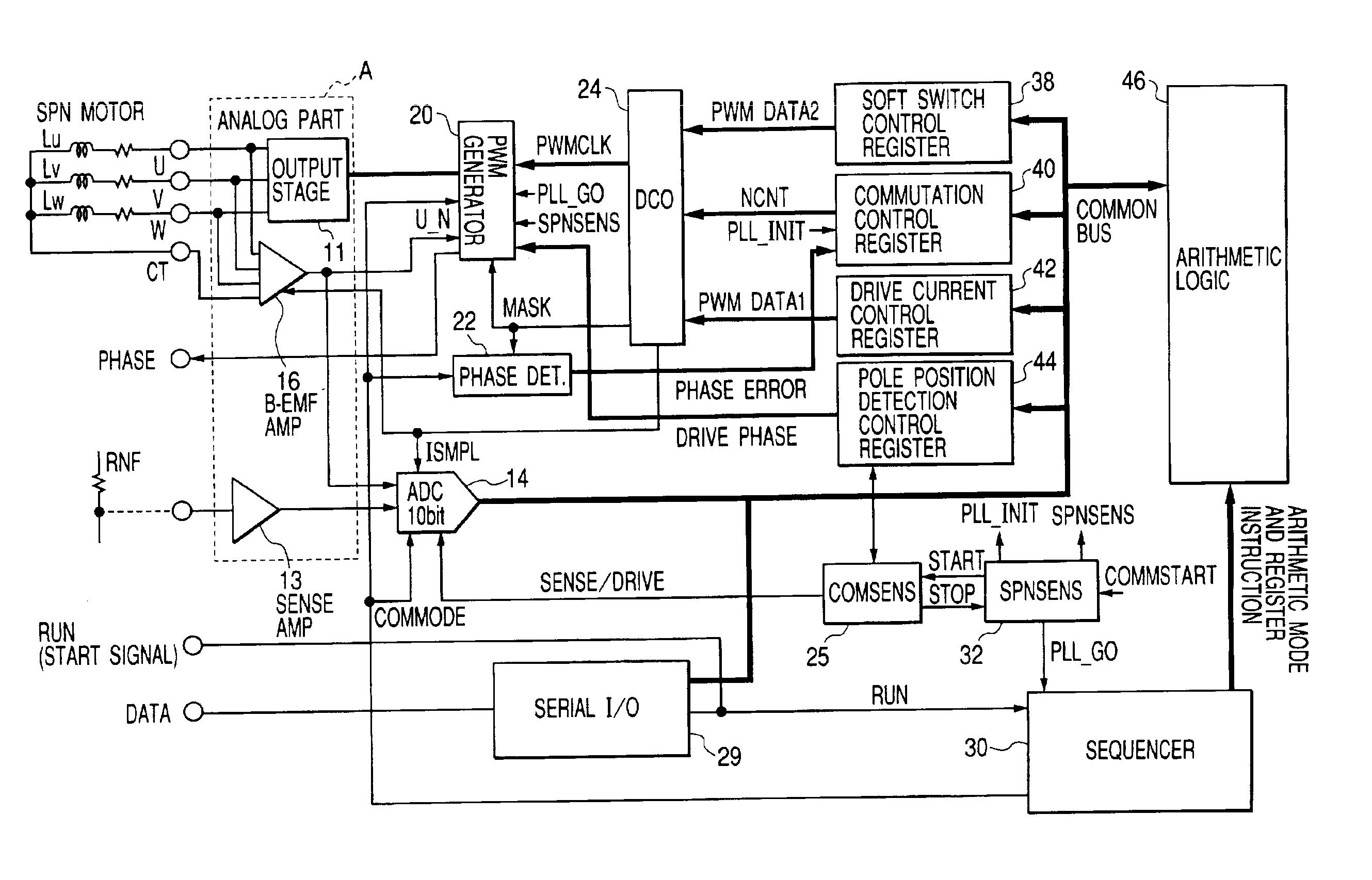
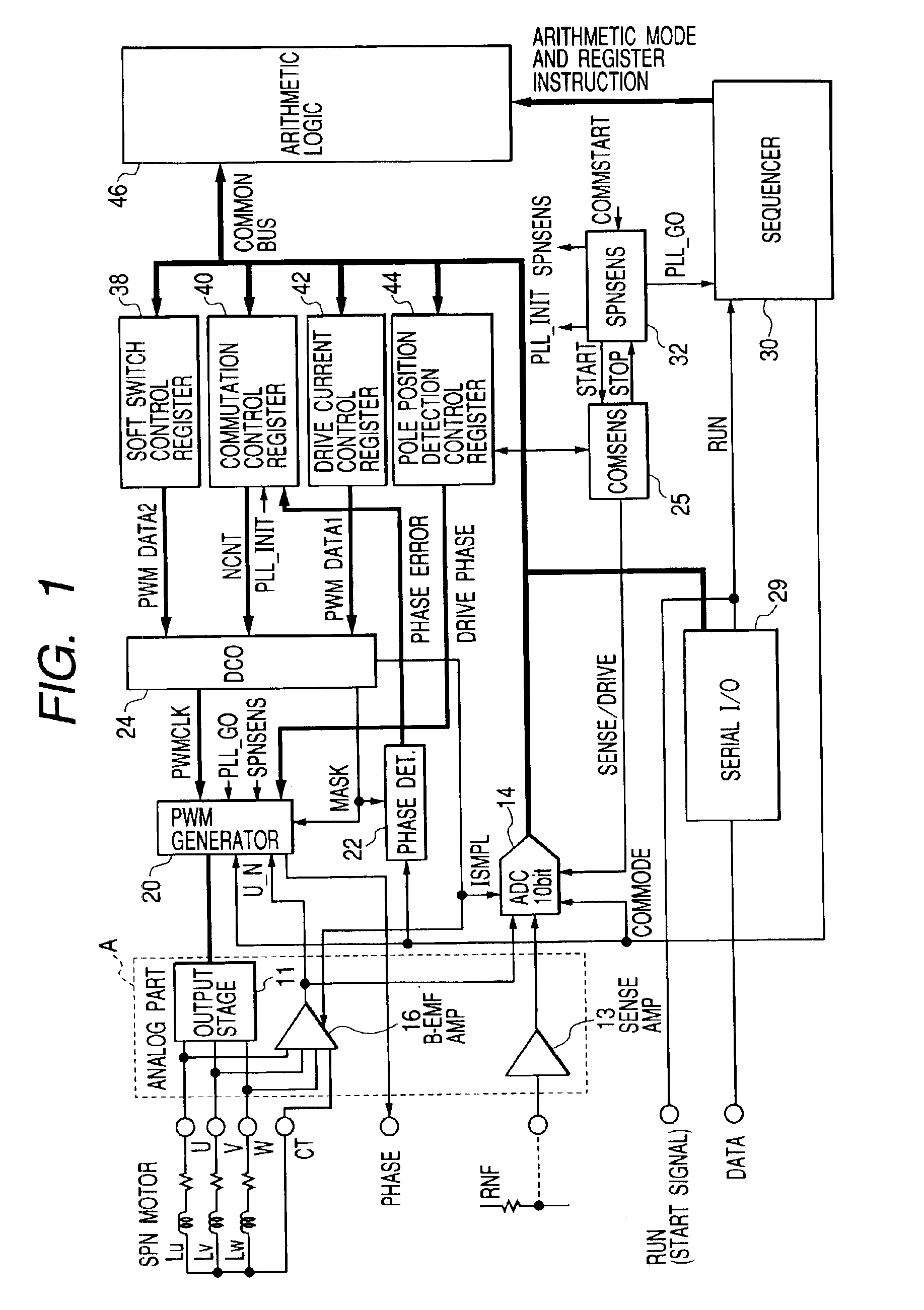
[0033]FIG. 1 schematically illustrates the drive control system for sensor-less motor to which the technique of the present invention is applied. The system illustrated in this figure is integrally formed on single semiconductor substrate using single crystalline silicon, except for the field coils Lu, Lv, Lw of motor. Moreover, the system illustrated in the same figure is formed of an analog signal processing part (within the frame of broken line A) and a digital signal processing part (outside of the frame of broken line A). Both circuit portions may be integrated on the single semiconductor substrate or formed separately on different semiconductor substrates as required. In regard to the digital signal processing part, a part or entire part of the function may be formed with a software using a microcomputer.

[0034]In FIG. 1, a sensor-less motor as the control obje...


PUM


Abstract

A drive control system, with PLL control, drives a rotatable multi-phase sensor-less motor by switching a current of a field coil of each phase depending on the rotating phase of the motor. When the moto is driven, a desired phase is selected as a datection phase, and a voltage induced on the coil of the detection phase is detected when power is fed for a predetermined time to the field coils other than the detection phase. A magnetic pole position is detected from the amplitude condition of the detected induced voltage. Based on this detection, the power-feeding phase of the motor drive is determined. Power feeding and pole position detection are performed alternately.

Description

BACKGROUND OF THE INVENTION[0001]The present invention relates to a drive control system for sensor-less motor and more specifically to the technique which may effectively be applied to the drive control of a brush-less DC multi-phase motor not including a rotation detecting sensor, for example, the technique which can be effectively applied to the drive control of a spindle motor for high speed drive of a disk storage medium (platter) of a HDD (hard disk drive)[0002]The HDD reads or writes information with the seeking and following operations of a magnetic head on a recording surface formed on the surface of platter while the disk type magnetic recording medium called the platter is rotated at a high speed. In order to realize high speed read / write operations of information in this HDD, the rotating speed of platter must be increased.[0003]The platter is driven to rotate with a spindle motor. For this spindle motor, a sensor-less motor is generally used. This sensor-less motor is a...

Claims


Application Information

Patent Timeline
Patent Type & Authority Patents(United States)
IPC IPC(8): H02P6/18H02P6/14H02P6/06H02P6/08
CPCH02P6/182Y10S388/911
Inventor KOKAMI, YASUHIKOKAWAUCHI, KUNIHIROTSUNODA, TOSHIYUKIKIMURA, REIICHI
Owner RENESAS SEMICON PACKAGE & TEST SOLUTIONS
Why Eureka
Try Eureka