System for providing electrical stimulation to a left chamber of a heart

a technology of electrical stimulation and left chamber, which is applied in the field of implantable medical electrical leads, can solve the problems of limiting the area of the tissue through which current flows during therapy, limiting the efficacy of high-voltage therapies, and difficulty in positioning multiple leads within the vasculatur

Inactive Publication Date: 2005-05-31
MEDTRONIC INC
View PDF18 Cites 95 Cited by
  • Summary
  • Abstract
  • Description
  • Claims
  • Application Information

AI Technical Summary

Problems solved by technology

Because of the small vessel size, positioning multiple leads within the vasculature is difficult.
Additionally, the size of coil electrodes of the type needed for high-voltage therapies may be limited based on the size of the vessels, thereby limiting the area of the tissue through which current flows during the therapy.
This may limit the efficacy of high-voltage therapies.
Finally, locating the leads at a precise location needed to provide adequate tissue stimulation may be difficult given the problems associated with navigating the torturous vessels such as the coronary sinus and branch veins.

Method used


Image

  • System for providing electrical stimulation to a left chamber of a heart
  • System for providing electrical stimulation to a left chamber of a heart
  • System for providing electrical stimulation to a left chamber of a heart

Examples


Embodiment Construction

[0027]The present invention provides a single lead system adapted for placement within a branch vein of the coronary sinus. This system is specifically sized to fit within the length and width of the branch vein.

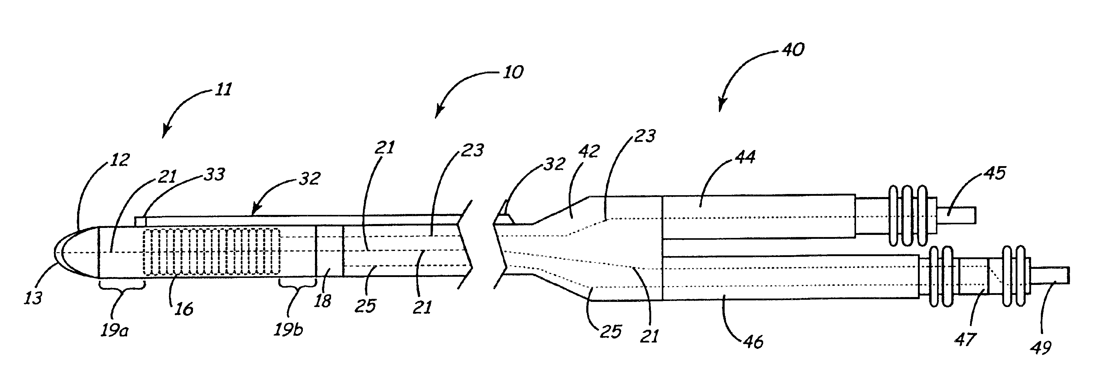
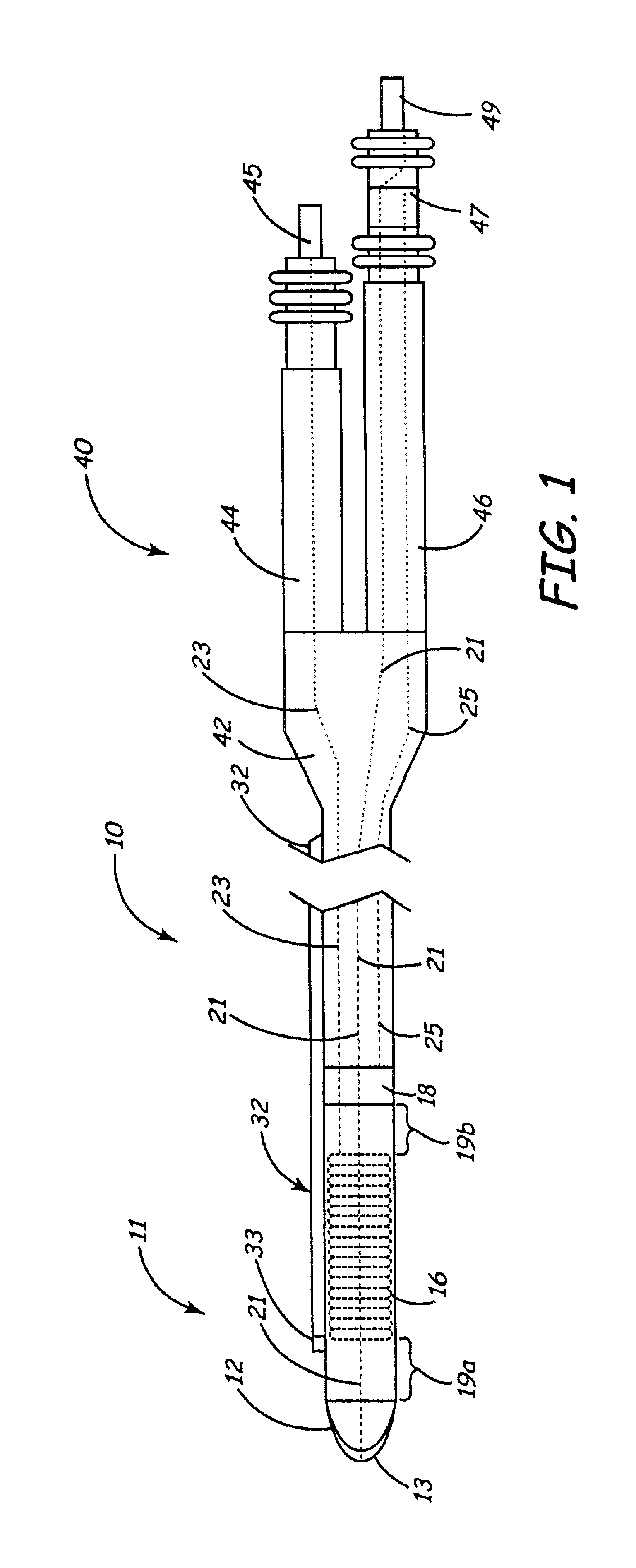
[0028]FIG. 1 is a plan view of one embodiment of the inventive lead system. The lead includes an elongated body 10 that may be of any conventional lead construction known in the art. For example, the exterior of lead may be formed of silicone, polyurethane, or a non-porous or dense PTFE.

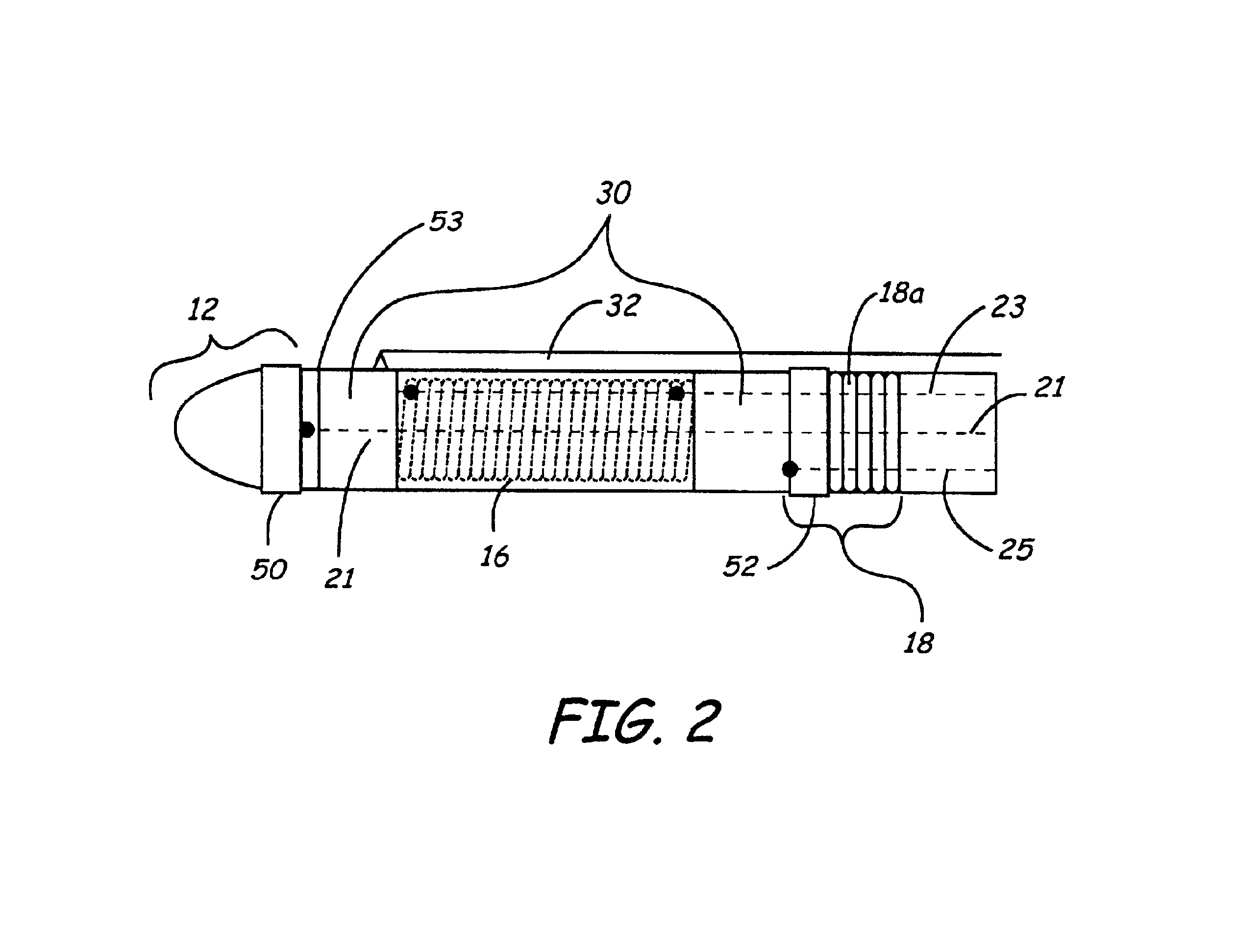
[0029]The distal end of the elongated body includes a tip electrode 12 for pacing and sensing in the left ventricle. This electrode could be any of the various types of pacing electrodes known in the art such as a porous platinized electrode assembly. A tip electrode is shown, although a ring electrode located proximate the distal end of the elongate body 10 could be used in the alternative. In one embodiment, this electrode is a steroid-eluting porous pacing electrode, as described in common...


PUM


Abstract

A medical electrical lead is disclosed that is adapted for placement in the coronary sinus, or a branch vein thereof. The lead includes a first and second pace / sense electrode. A selection mechanism is provided to select either the first or the second electrode for use as a cathode, with the other electrode being selected as the anode. According to another aspect of the invention, a high-voltage coil electrode may be provided between the first and second electrodes. The coil electrode may be electrically coupled to the anode to increase the shadow area of the coil electrode.

Description

RELATED APPLICATIONS[0001]This Application claims priority to provisionally-filed U.S. Patent Application Ser. No. 60 / 258,651 filed Dec. 29, 2000 entitled “Medical Electrical Lead”, which is incorporated herein by reference in its entirety.FIELD OF THE INVENTION[0002]The present invention relates generally to an implantable medical electrical lead; and more particularly, relates to a medical electrical lead system for implantation in a cardiac vein.BACKGROUND OF THE INVENTION[0003]It has long been known that implantable medical electrical leads may be positioned transvenously within one or more chambers of the heart to provide electrical stimulation to, and to monitor signals occurring within, the cardiac tissue. In order to achieve reliable sensing of the cardiac electrogram and / or to apply stimulation that effectively paces or cardioverts the heart chamber, it is necessary to accurately position the electrode surface against the endocardium or within the myocardium at the desired ...

Claims


Application Information

Patent Timeline
Patent Type & Authority Patents(United States)
IPC IPC(8): A61N1/05
CPCA61N1/056A61N2001/0585
Inventor DAHL, ROGERSOUKUP, THOMAS M.PERTTU, JOETHORNTON, ARNOLDBELDEN, ELISABETH L.SOMMER, JOHN L.
Owner MEDTRONIC INC
Why Eureka
Try Eureka