Tensegrity unit, structure and method for construction

a tension member and construction technology, applied in the direction of girders, joists, building roofs, etc., can solve the problems of affecting the assembly and load bearing ability of the structure, collisions between compression members, and tangling of tension members, and achieve the effect of convenient positioning

Inactive Publication Date: 2005-06-07
BOARD OF RGT THE UNIV OF TEXAS SYST
View PDF14 Cites 47 Cited by
  • Summary
  • Abstract
  • Description
  • Claims
  • Application Information

AI Technical Summary

Benefits of technology

[0020]A tensegrity unit may be formed of compression members and tension members. In a deployed state, the tensegrity unit may be coupled to other tensegrity units to form a tensegrity structure. In a non-deployed state, the compressio

Problems solved by technology

For structures of significant size, issues such as tangling of tension members and collisions between compression members may become quite difficult to solve.
In some other types of deployable structures, such as scissor structures, minor inaccuracies in tension member lengths and/or compression member lengths may significantly affect structure assembly and load bearing ability.
Such connections may require complex joints if the resulting structure is intended to be collapsible.
Tensegrity structures may possess a high level of structural redundancy.
Aligning bars in this manner may be difficult to achieve with the unit on the ground, especially since the bars tend to collapse in a symmetric pattern around the center of the unit.
Positioning the compression members and the tension members and setting the final tens

Method used


Image

  • Tensegrity unit, structure and method for construction
  • Tensegrity unit, structure and method for construction
  • Tensegrity unit, structure and method for construction

Examples


Embodiment Construction

[0039]Several basic functionality requirements may be desirable in a tensegrity unit. Desirable functionality requirements may include:

[0040]1) the number of steps in the deployment and / or collapse of the unit, including the number of joints that require manual control, should be kept to a minimum;

[0041]2) the deployment and / or collapse process should not involve loose cable ends;

[0042]3) the deployment and / or collapse should not require tension member length change; an

[0043]4) the unit should collapse as a bundle in an upright position.

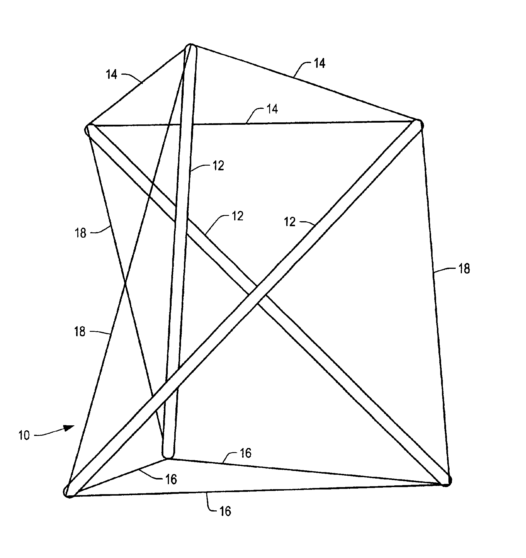
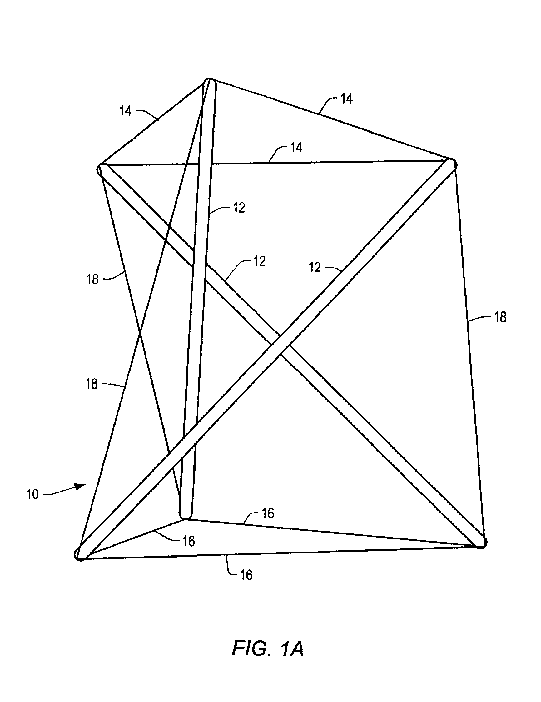
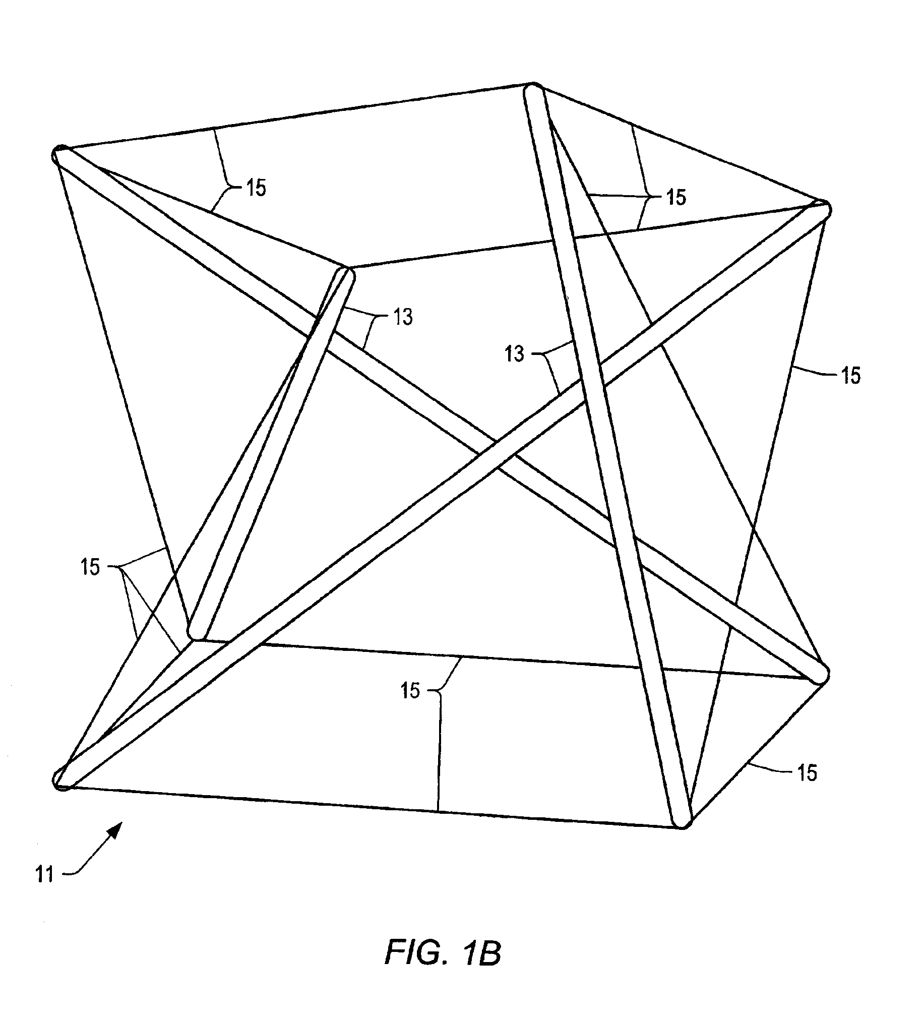
[0044]FIG. 2 depicts an embodiment of tensegrity unit 30. Tensegrity unit 30 may include compression members 32, face tension members 34, and continuous tension members 36 (dotted line), 38 (bold line), 40 (dashed line), and 42 (alternating dotted and dashed line). Tensegrity unit 30 may have a skewed prism geometric shape. The amount of skew may depend on the number of compression members in the tensegrity unit. For example, a tensegrity unit having...


PUM


Abstract

Tensegrity units may be used to form a tensegrity structure. Each tensegrity unit may include n face tension members, n continuous tension members, and n compression members. A bracket for the tensegrity unit may allow for adjustment of position of portions of the tension members when the tensegrity unit is not in a deployed state. The tension members may be coupled to the tensegrity unit so that there are no loose tension member ends. The unit may be deployed from a collapsed state by positioning the compression members and tension members in a proper orientation and adjusting the length of at least one compression member. Adjusting the length of at least the one compression member may allow tension to be applied to each tension member. A tensegrity structure may be formed from tensegrity units by joining a number of tensegrity units together.

Description

PRIORITY CLAIM[0001]This application claims priority to U.S. Provisional Application No. 60 / 294,427 entitled “Tensegrity Unit, Structure and Method for Construction,” filed May 29, 2001. The above-referenced provisional application is hereby incorporated by reference as if fully set forth herein.BACKGROUND OF THE INVENTION[0002]1. Field of the Invention[0003]The present invention relates generally to a tensegrity structure. An embodiment of the invention relates to a tensegrity unit that has no loose bars or cables in a collapsed state, and that may be easily and rapidly deployed. Several tensegrity units may be coupled together to assemble a tensegrity structure.[0004]2. Description of Related Art[0005]A tensegrity unit is a self-stressed equilibrium network in which a continuum of tension members (e.g., cables) interacts with a discontinuous system of compression members (e.g., bars) to provide the unit with structural integrity. The tension members may be cables, lines, chains, o...

Claims


Application Information

Patent Timeline
IPC IPC(8): E04B1/32E04B1/19
CPCE04B1/19E04B1/3211E04B2001/1927E04B2001/196E04B2001/1981Y10S52/10E04B2001/1993E04B2001/1996E04B2001/3235E04B2001/3241E04B2001/1987
Inventor LIAPI, KATHERINE A.
Owner BOARD OF RGT THE UNIV OF TEXAS SYST
Why Eureka
Try Eureka