
Pole reinforcing arrangement

a technology of reinforcing arrangement and poles, which is applied in the direction of pillars, foundation engineering, building components, etc., can solve the problems of increasing the number of poles, the number of out-dated steel poles is not enough, and the pole cannot be used anymore, so as to increase the strength of the poles

Inactive Publication Date: 2005-06-07
PENNSUMMIT TUBULAR
View PDF15 Cites 60 Cited by
  • Summary
  • Abstract
  • Description
  • Claims
  • Application Information

AI Technical Summary

Benefits of technology

[0018]It is an object of the present invention to provide a new and improved arrangement for reinforcing poles or retrofitting poles to increase their strength.
[0020]It is still another object of the present invention to provide a new and improved arrangement for reinforcing poles which is easily attached to an exterior of the pole.
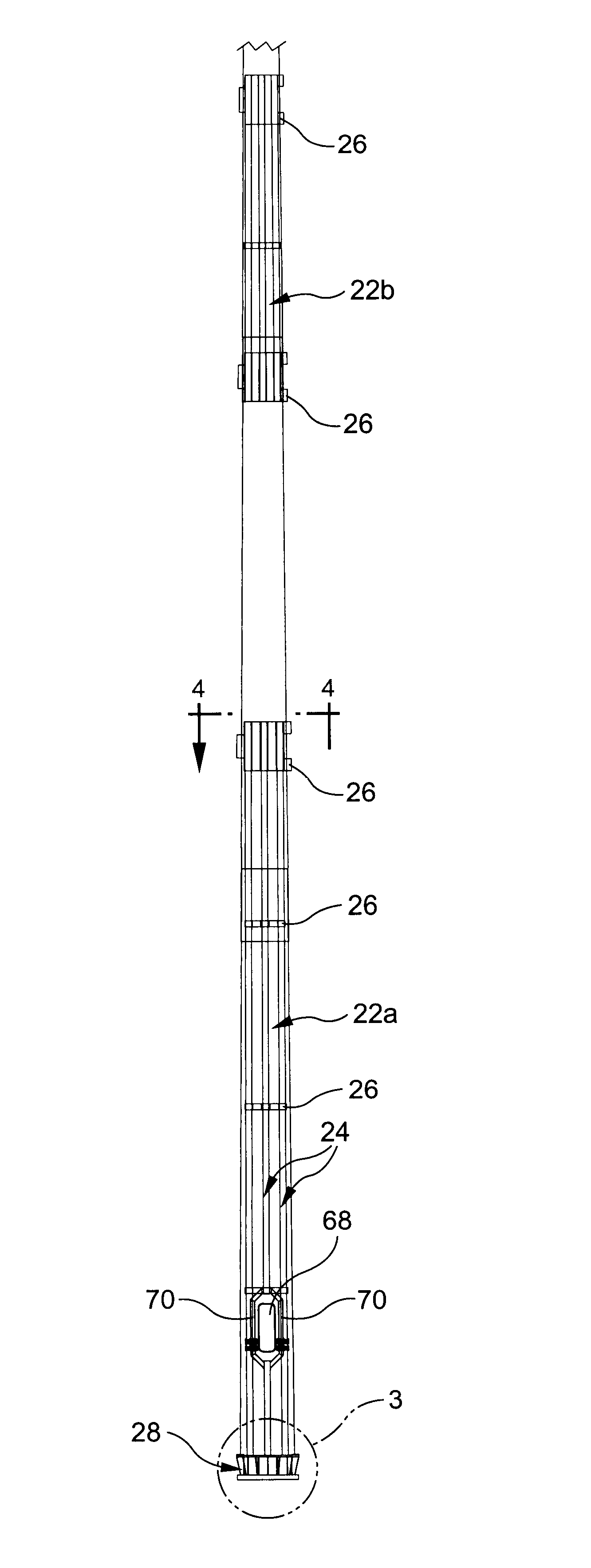
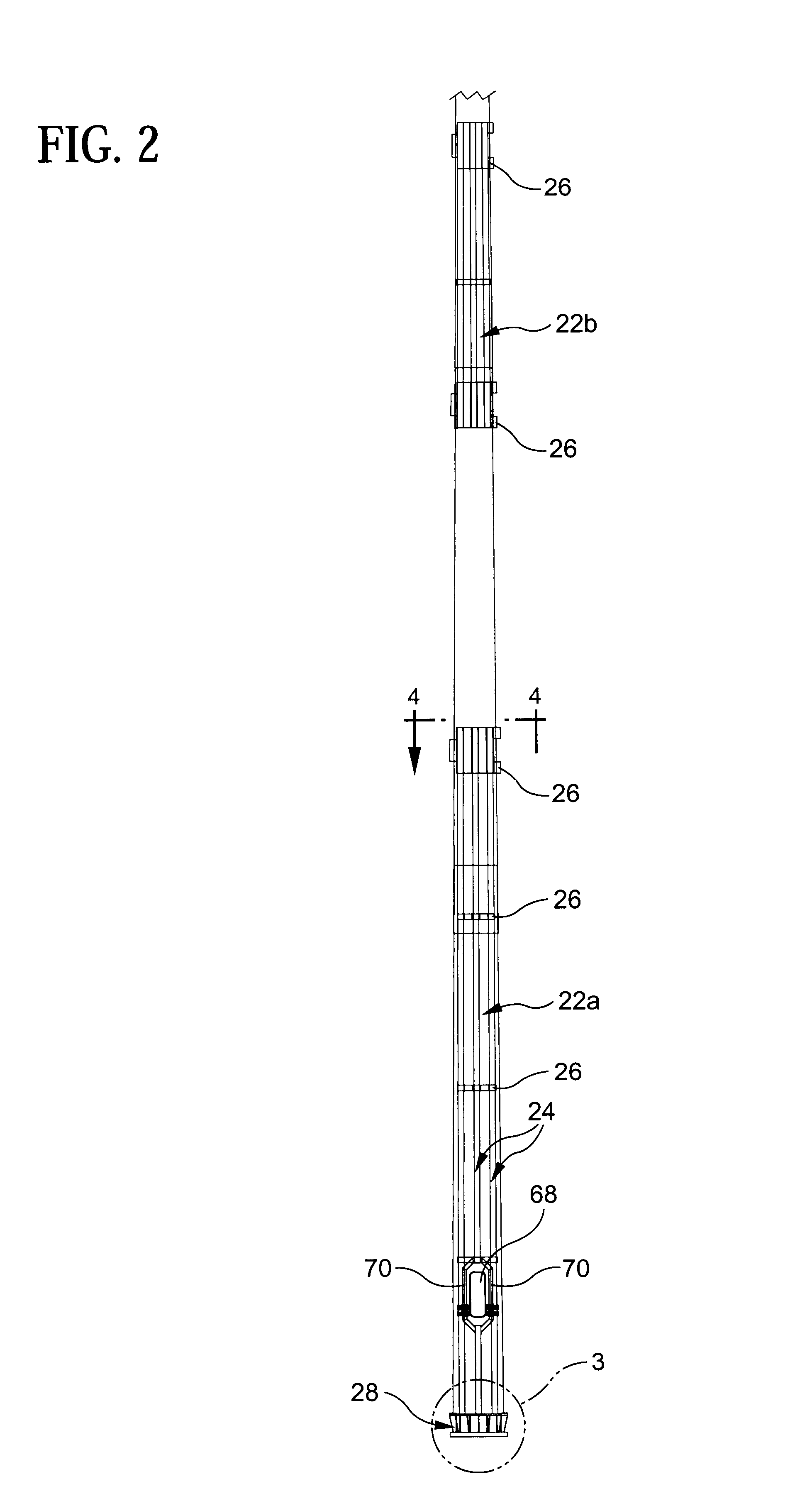
[0028]Another embodiment of a reinforcement arrangement for a pole in accordance with the invention comprises elongate supports adapted to be attached to the base plate of the pole at discrete locations around a circumference of the column and extend vertically alongside the column and annular clamping collars adapted to be arranged around the column of the pole at different vertical locations. The clamping collars engage with the tubes to thereby form a skeletal framework around the column. This skeletal framework provides increased load-bearing capability to the pole which enables installation of additional antennas on the pole.

Problems solved by technology

One problem facing the wireless industry in the face of increasing competition and public opposition to new wireless site construction is thousands of out-dated steel poles under-designed for the present needs of the industry.
Another problem that may arise is that poles might be manufactured with the expectation of supporting a set number of antennas but prior to installation, the number of antennas needed or desired for installation on the pole has increased so that the pole can no longer be used.
Unless an alternative installation site is found which requires no more than the original set number of antennas, the pole has been rendered useless.
Another problem arises when it is desired to replace communication antennas with larger antennas.
The pole as originally constructed might not be capable of supporting the increased area.
None of these patents provides a reliable reinforcement system for a pole which is easily assembled and versatile.

Method used


Image

  • Pole reinforcing arrangement
  • Pole reinforcing arrangement
  • Pole reinforcing arrangement

Examples


Embodiment Construction

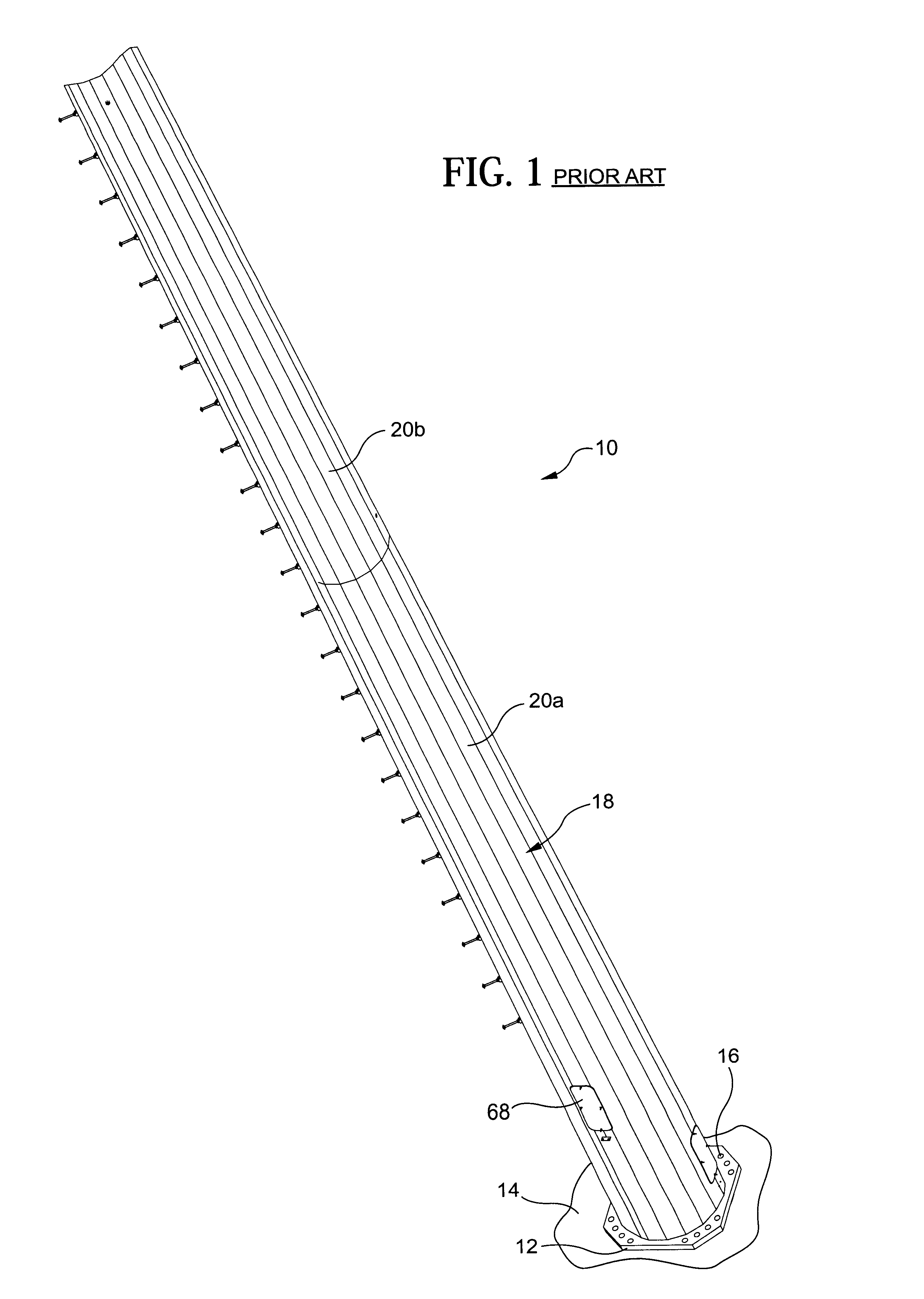
[0064]Referring initially to FIG. 1, a typical pole for supporting wireless communication antennas currently in use (and which is often referred to as a monopole type of antenna supporting structure or monopole) is designated generally at 10 and includes a base plate 12 connected to a foundation 14 by anchor bolts or similar attachment means 16 and a column 18 connected to the base plate 12. Column 18 may comprise one or more segments, e.g. two segments 20a, 20b as shown in FIG. 1, and means for enabling attachment of one or more communication antennas (not shown). Additional equipment is also connected to the column 18, e.g., a support platform, or housed within the column 18, e.g., electronic communication devices.

[0065]As discussed above, a typical prior art monopole 10 was usually designed to support only a set of one or more antennas of a single communication provider. It is not assured that the monopole 10 would be capable of supporting multiple sets of antennas, i.e., antenna...


PUM


Abstract

Reinforcement arrangement for a pole including abase flange surrounding a bottom of the pole, elongate tubes connected to the base flange and arranged at discrete locations around a circumference of the pole to extend vertically alongside the pole and annular clamping collars arranged around the pole at different vertical locations. The tubes are attached to the clamping collars to thereby form a skeletal framework around the pole which provides increased load-bearing capability to the pole and enables installation of additional antennas on the pole. The base flange is supported above the base plate by gussets which are welded to the base plate and pole. The clamping collars are each formed from several collar segments, each extending partially around the circumference of the pole with adjacent collar segments being attached to one another.

Description

CROSS-REFERENCE TO RELATED APPLICATION[0001]This application claims priority under 35 U.S.C. §119(e) of U.S. provisional patent application Ser. No. 60 / 291,539 filed on May 16, 2001, which is incorporated by reference herein.FIELD OF THE INVENTION[0002]The present invention relates generally to an arrangement for reinforcing poles or retrofitting poles to increase their strength and more particularly to an arrangement for reinforcing poles that support one or more communication antennas to enable such poles to support additional antennas.[0003]The present invention also relates to reinforced poles and retrofitted poles in particular, poles for supporting communication antennas.BACKGROUND OF THE INVENTION[0004]The growth of the wireless industry in the United States can be traced to the introduction of cellular service in the mid-1980's. The increase in mounting sites for wireless antennas is evidenced by the fact that in January 1985, there were only about 346 whereas in July 2000, ...

Claims


Application Information

Patent Timeline
Patent Type & Authority Patents(United States)
IPC IPC(8): E04C3/30E04H12/22E04C3/34
CPCE04H12/2292E04C3/34
Inventor BRUNOZZI, JEFFREY R.REESE, BRIAN R.HAWKINS, DAVID D.
Owner PENNSUMMIT TUBULAR
Learn More