
Exhaust gas purifying method, exhaust gas purifying apparatus, and exhaust gas collecting apparatus of internal combustion engine

a technology of exhaust gas purification and exhaust gas collection, which is applied in mechanical equipment, machines/engines, separation processes, etc., can solve the problems of excessive heating of catalytic converters, thermal degradation of catalytic converters, and insufficient purification performance of catalytic converters, so as to restrict the discharging of harmful components

Inactive Publication Date: 2005-06-07
TOYOTA JIDOSHA KK
View PDF21 Cites 36 Cited by
  • Summary
  • Abstract
  • Description
  • Claims
  • Application Information

AI Technical Summary

Benefits of technology

[0007]It is an object of the present invention to provide an exhaust gas purifying method and an exhaust gas purifying apparatus that restrict the discharging of harmful components when the catalytic converter is not sufficiently warmed up immediately after the starting of the internal combustion engine, by using means other than the absorbent or the like. It is also an object of the present invention to provide an exhaust gas collecting apparatus that can be suitably used for the method and the apparatus.

Problems solved by technology

A catalytic converter that is used to purify the exhaust gas from an internal combustion engine has such characteristics that the catalytic converter cannot sufficiently exhibit its purification performance unless the catalytic converter is heated to a predetermined temperature range for activation.
However, when the catalytic converter is set close to the exhaust port, the catalytic converter is heated excessively after the warming up, and the catalytic converter is thermally degraded.
In this case, the manufacturing cost of the catalytic converter increases.
When the zeolite catalyst is not yet saturated, the exhaust gas is not collected even if the catalytic converter is not sufficiently warmed up.
Consequently, the structure of the exhaust gas purifying apparatus becomes complex, and it takes time and labor to manufacture and maintain the apparatus.

Method used


Image

  • Exhaust gas purifying method, exhaust gas purifying apparatus, and exhaust gas collecting apparatus of internal combustion engine
  • Exhaust gas purifying method, exhaust gas purifying apparatus, and exhaust gas collecting apparatus of internal combustion engine
  • Exhaust gas purifying method, exhaust gas purifying apparatus, and exhaust gas collecting apparatus of internal combustion engine

Examples


first embodiment

(First Embodiment)

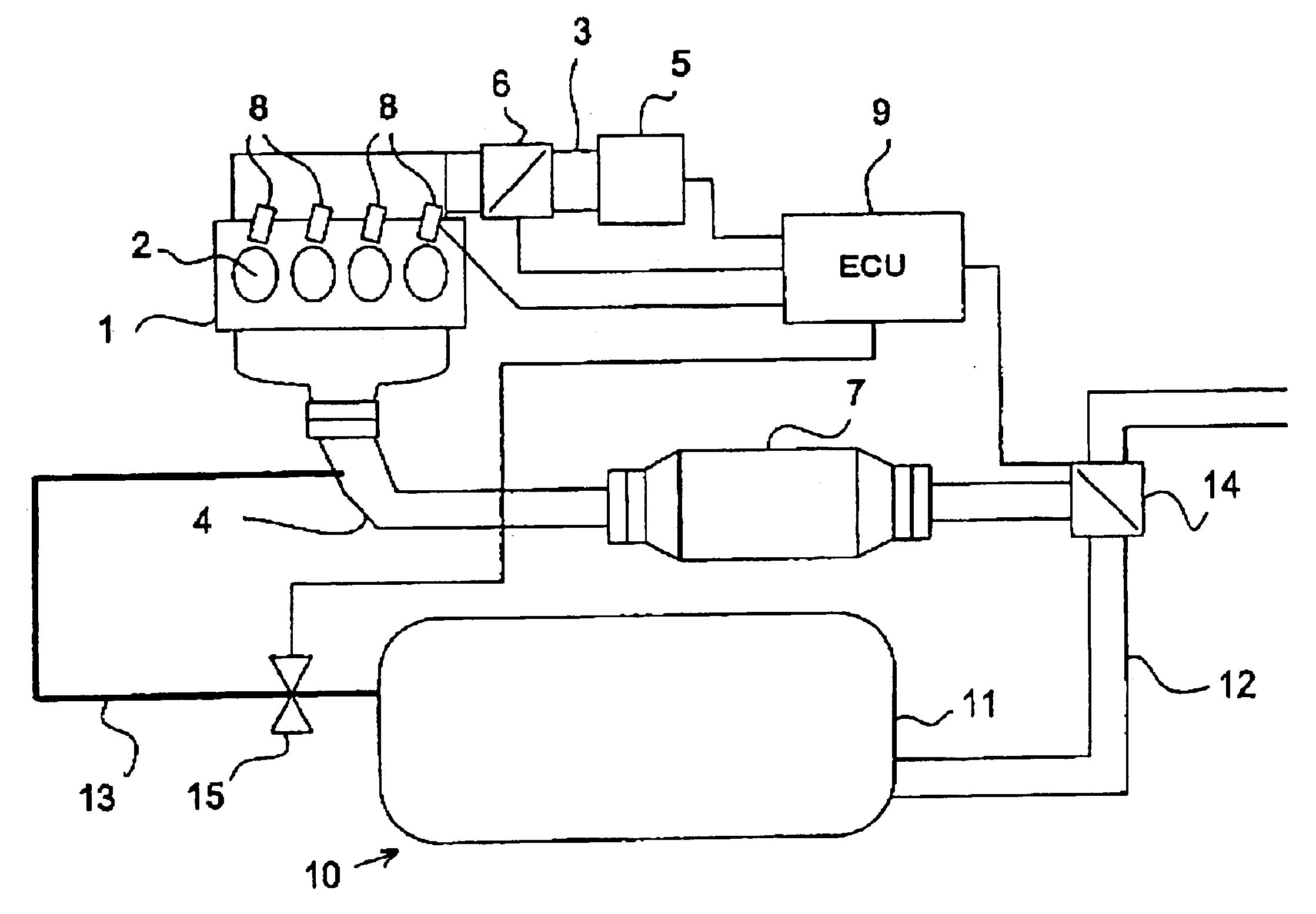
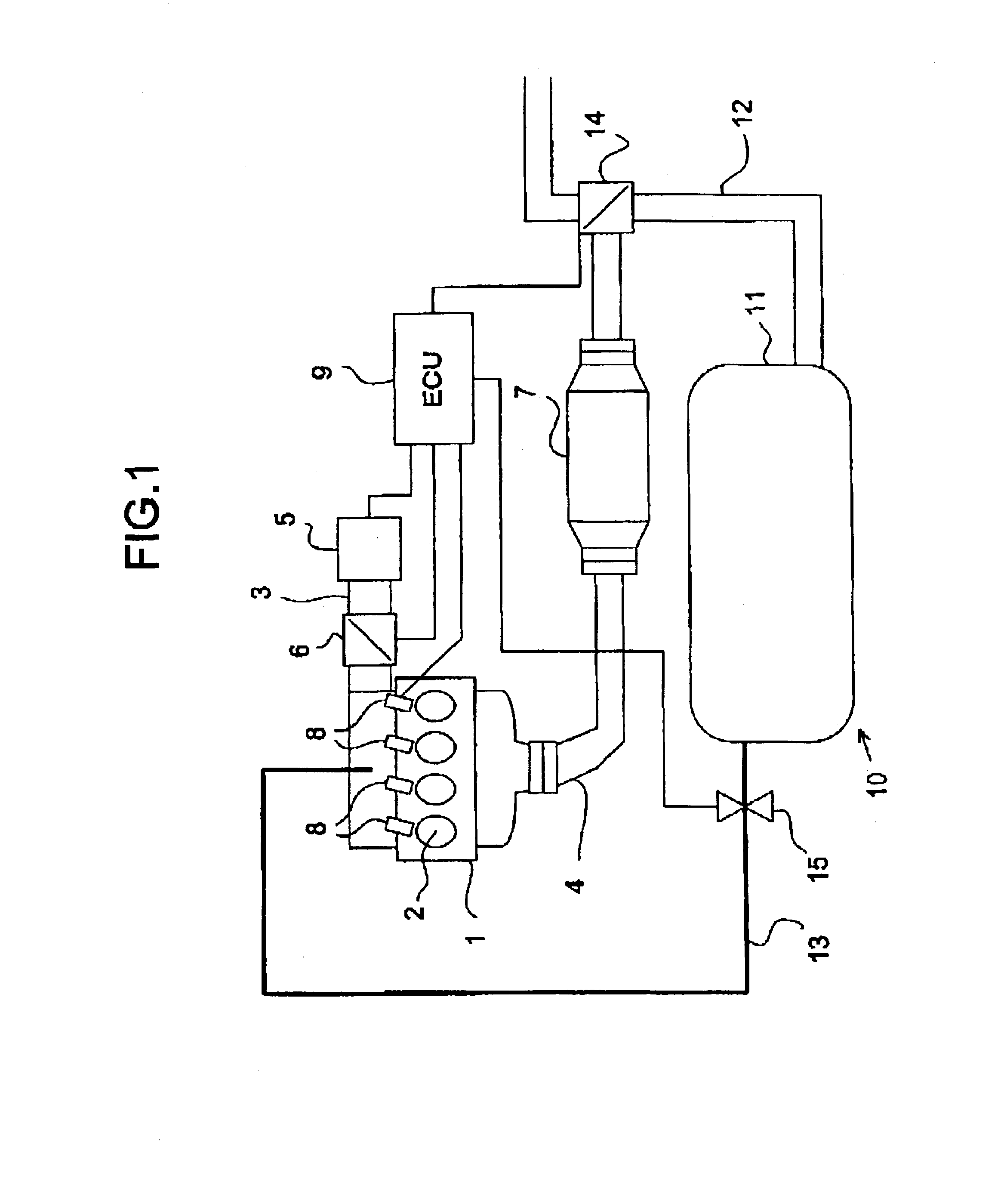
[0042]FIG. 1 shows a structure of an exhaust gas purifying apparatus according to a first embodiment of the present invention. In FIG. 1, an internal combustion engine 1 is structured as a four-cylinder engine that has four cylinders 2, . . . , and 2 disposed in-line. As is well known in the art, the internal combustion engine has an intake passage 3 and an exhaust passage 4 connected thereto. The intake passage 3 is provided with an air filter 5 that filters an intake gas, and a throttle valve 6 for adjusting an intake quantity. The exhaust passage 4 is provided with a three-way catalytic converter 7 that purifies the exhaust gas. The internal combustion engine 1 is provided with injectors (i.e., fuel injection valves) 8, . . . , and 8, corresponding to the cylinders 2. The injectors 8 may be provided to jet fuel to the intake passage 3, or may be provided to jet fuel into the cylinders 2. The internal combustion engine 1 may be of a spark ignition type or a self-...

second embodiment

(Second Embodiment)

[0057]An exhaust gas purifying apparatus according to a second embodiment of the present invention will be explained with reference to FIG. 5 and FIGS. 6A to 6C. In these drawings, portions identical to those in FIG. 1 and FIG. 2 are attached with like reference numerals, and their explanation will be omitted.

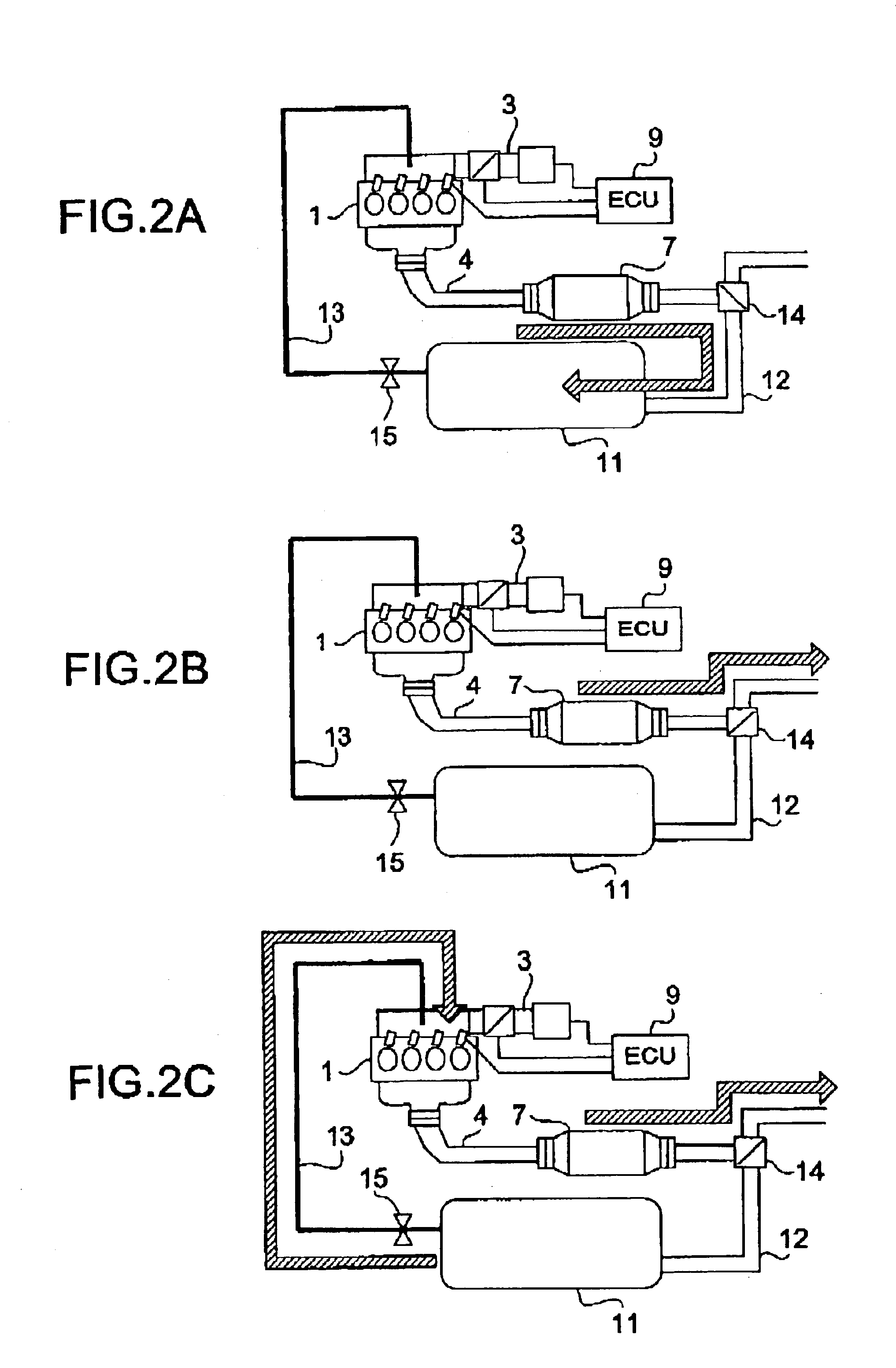
[0058]The exhaust gas purifying apparatus according to the second embodiment shown in FIG. 5 is different from the exhaust gas purifying apparatus according to the embodiment shown in FIG. 1 in that the exhaust gas introduction passage 13 is connected to the exhaust passage at a position upstream from the catalytic converter 7. Other points are similar to those shown in FIG. 1. Therefore, when the open / close valve 15 is opened, the exhaust gas held in the collection vessel 11 is introduced to the exhaust passage 4, and is supplied to the catalytic converter 7, as shown in FIG. 6C. When the exhaust gas is recirculated to the exhaust passage 4 in this way, the ...

third embodiment

(Third Embodiment)

[0060]An exhaust gas purifying apparatus according to a third embodiment of the present invention will be explained with reference to FIG. 7 to FIG. 10. In these drawings, portions identical to those in FIG. 1 and FIG. 2 are attached with like reference numerals, and their explanation will be omitted.

[0061]In the embodiment shown in FIG. 7, the exhaust gas taking-out passage 12 is branched from the exhaust passage 4 at a position upstream from the catalytic converter 7. The switching valve 14 is switchable between an exhaust gas discharging position where the exhaust gas is introduced to the catalytic converter 7 as shown in FIG. 8B and an exhaust gas collecting position where the exhaust gas is introduced to the exhaust gas taking-out passage 12 as shown in FIG. 8A. A heater 20 as a heating device is provided between the switching valve 14 and the catalytic converter 7. The heater 20 may be an electric heater, or a burner. When the electric heater is utilized as t...


PUM


Abstract

An exhaust gas collecting apparatus, of an internal combustion engine including a collection vessel that can hold exhaust gas, an exhaust gas taking-out passage through which exhaust gas is introduced from an exhaust passage to the collection vessel, an exhaust gas introduction passage through which the exhaust gas is introduced from the collection vessel to the exhaust passage at a position upstream from the catalytic converter, a first valve that is switchable between a position where the introduction of the exhaust gas from the exhaust passage to the exhaust gas taking-out passage is permitted and a position where the introduction of the exhaust gas is prevented, and a second valve that is switchable between a position where the introduction of the exhaust gas through the exhaust gas introduction passage is permitted and a position where the introduction of the exhaust gas is prevented.

Description

BACKGROUND OF THE INVENTION[0001]1. Field of the Invention[0002]The present invention relates to an exhaust gas purifying method and an exhaust gas purifying apparatus of an internal combustion engine, and an exhaust gas collecting apparatus that can be used for the method and the apparatus.[0003]2. Description of the Related Art[0004]A catalytic converter that is used to purify the exhaust gas from an internal combustion engine has such characteristics that the catalytic converter cannot sufficiently exhibit its purification performance unless the catalytic converter is heated to a predetermined temperature range for activation. Therefore, various attempts are made to activate the catalytic converter rapidly. For example, the catalytic converter is disposed as close as possible to the exhaust port of the internal combustion engine. Alternatively, a delay control is carried out to intentionally delay the ignition timing at the time of cold start, thereby to try to rapidly activate t...

Claims


Application Information

Patent Timeline
Patent Type & Authority Patents(United States)
IPC IPC(8): F01N3/20F02M25/07B01D53/94F01N3/08F01N3/18F01N3/24F02D21/08
CPCF01N3/20F01N3/2013F02M25/0743F02M25/0718F01N2240/26Y02T10/26Y02T10/121F02M26/15F02M26/37Y02T10/12
Inventor ASANUMA, TAKAMITSUTANAKA, TOSHIAKIHIROTA, SHINYAUEDA, TAKANORIYAMASHITA, TETSUYANAKANO, YASUAKI
Owner TOYOTA JIDOSHA KK
Learn More