Semi-solid molding apparatus and method

a molding apparatus and semi-solid technology, applied in the direction of metal founding, chemical apparatus and processes, etc., can solve the problems of inability to reuse process offal, severe limitations on the commercial application of ssm processes, etc., and achieve high and reliable strength and ductility, reduce the cost of producing parts, and close dimensional tolerances

Inactive Publication Date: 2005-06-07
THT PRESSES INC
View PDF15 Cites 16 Cited by
  • Summary
  • Abstract
  • Description
  • Claims
  • Application Information

AI Technical Summary

Benefits of technology

[0003]The present invention is directed to a new SSM method and apparatus which significantly reduces the costs of producing parts by the SSM process. The method and apparatus of the invention is ideally suited for producing parts having thin sections, fine detail and complexity and close dimensional tolerances, and which are substantially free of porosity and oxides, can be processed at elevated temperatures without blistering and which can provide high and reliable levels of strength and ductility. The method and apparatus of the invention avoids any need to produce a specially treated, pre-cast billet that must be sawed to length before using or a slurry especially prepared from molten alloy in equipment external to the die casting press. The method and apparatus of the invention is also applicable to a wide variety of alloys, for example, standard A356 alloy and alloys of the Al—Si, Al—Cu, Al—Mg and Al—Zn families, all of which can be acquired in the form of and at prices normal to conventional foundry ingot, including both primary and secondary origin.

Problems solved by technology

The cost premiums associated with either the pre cast specially treated billet that must be sawed to length before using, or the slurry especially prepared in equipment external to the die casting press, have severely limited the commercial applications of the SSM processes.
Also, the pre-cast billet is available from a relatively few sources, is currently made only from primary alloys, and process offal cannot be reused unless reprocessed back into a billet.

Method used


Image

  • Semi-solid molding apparatus and method
  • Semi-solid molding apparatus and method
  • Semi-solid molding apparatus and method

Examples


Embodiment Construction

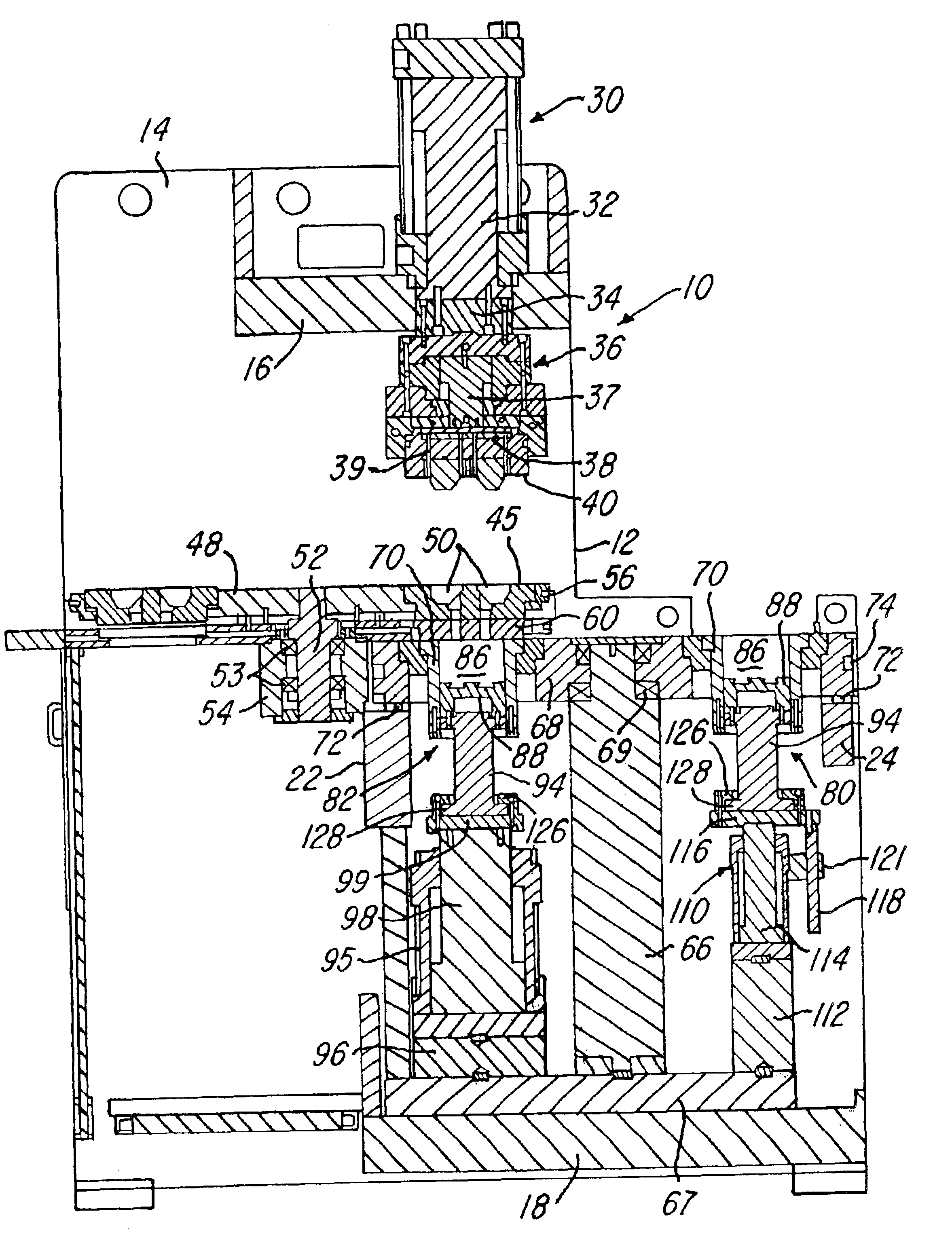
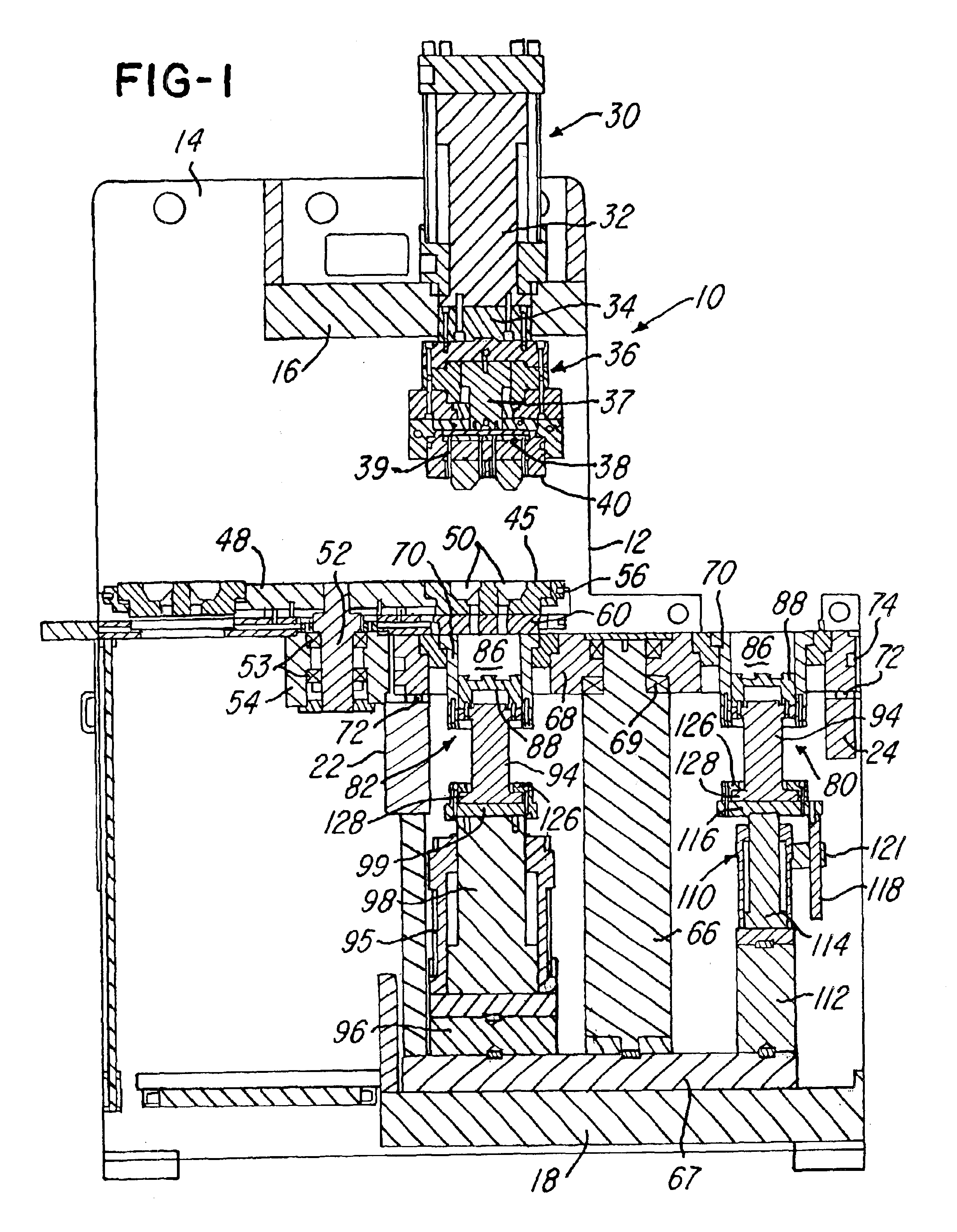
[0013]Referring to FIG. 1, a vertical die cast machine or press 10 is constructed similar to the press disclosed in U.S. Pat. No. 5,660,223 which issued to the assignee of the present invention and the disclosure of which is incorporated by reference. The press 10 includes a frame 12 formed by a pair of parallel spaced vertical side walls or plates 14 rigidly connected by top plate 16 a base or bottom plate 18 and a set of intermediate cross plates or bars 22 and 24 all rigidly secured to the side panels 14. The top cross plate 16 supports an upper double acting hydraulic clamping cylinder 30 having a piston rod 32 projecting downwardly on a vertical center axis of the press. The piston rod 32 carries an adapter plate 34 which supports a hydraulic ejector cylinder 36 having a piston 37 projecting downwardly to support a plate 38 which carries a set of ejector pins 39.

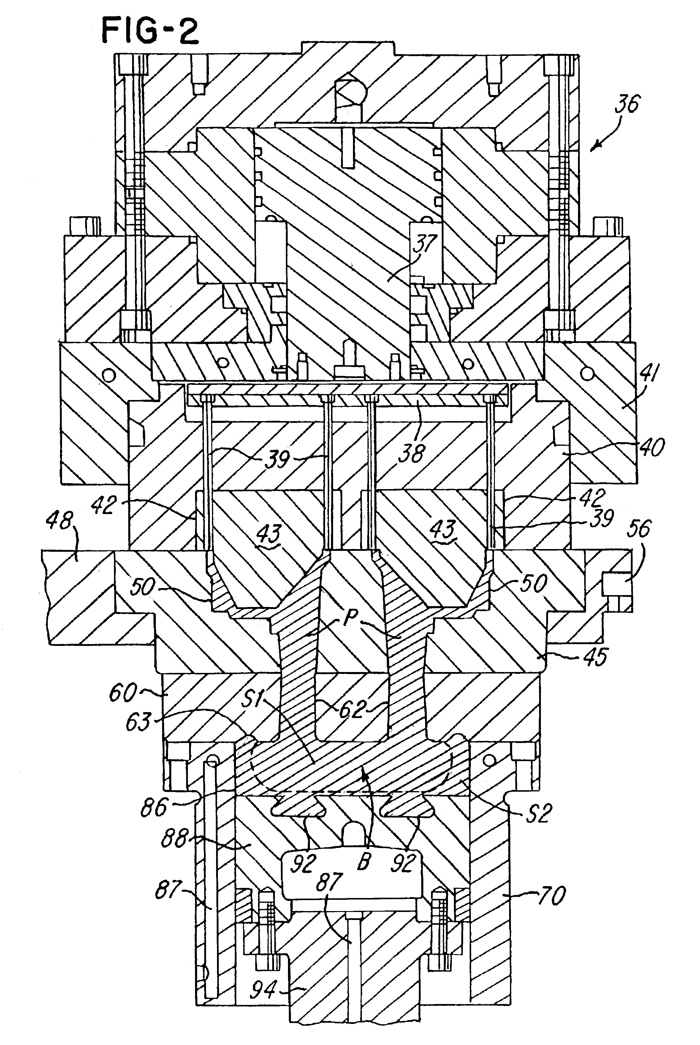
[0014]An upper die or mold section 40 (FIG. 2) is secured to the bottom of the plate 38 by an annular retaining plate...


PUM

PropertyMeasurementUnit
temperatureaaaaaaaaaa
diameteraaaaaaaaaa
temperatureaaaaaaaaaa

Abstract

A metal alloy is heated to a molten state and is poured into a shot sleeve of a vertical die cast press and on top of a shot piston. The shot sleeve is transferred to an injection station while the molten alloy is cooled to a semi-solid slurry and a globular, generally non-dendritic microstructure. A retractable cooling pin is temporarily inserted into a center portion of the slurry while in the shot sleeve to obtain optimum cooling. A center portion of the slurry is injected upwardly by the piston through a gate opening into a die cavity while an outer more solid portion of the slurry is entrapped in an annular recess. After the slurry solidifies, the shot piston retracts, and the shot sleeve is transferred to a position where the residual biscuit is removed. Another shot sleeve filled with the molten allow is transferred, and the process is repeated.

Description

BACKGROUND OF THE INVENTION[0001]The present invention relates to semi-solid molding (SSM) of metal alloys and the equipment and methods used for SSM, and which are disclosed in many U.S. and foreign patents, for example, in U.S. Pat. Nos. 3,954,455, 4,434,837, 5,161,601 and 6,165,411. SSM is also discussed in technical publications, for example, in a book entitled Science and Technology of Semi-Solid Metal Processing, published by North American Die Casting Association in October, 2001. Chapter 4 of this publication was authored by a co-inventor of the present invention. In conventional SSM processes, it is necessary to use either a specially treated, pre-cast billet of appropriate microstructure or a slurry especially prepared from molten alloy in equipment external to a die casting press. The cost premiums associated with either the pre cast specially treated billet that must be sawed to length before using, or the slurry especially prepared in equipment external to the die casti...

Claims


Application Information

Patent Timeline
Patent Type & Authority Patents(United States)
IPC IPC(8): B22D17/00B22D17/08B22D17/12B22D21/04B22D17/20B22D27/20
CPCB22D17/007B22D17/12Y10S164/90
Inventor KAMM, RICHARD J.JORSTAD, JOHN L.
Owner THT PRESSES INC
Why Eureka
Try Eureka