Variable torque impact wrench

Active Publication Date: 2005-06-07
HUBBELL INC
View PDF25 Cites 40 Cited by
  • Summary
  • Abstract
  • Description
  • Claims
  • Application Information

AI Technical Summary

Benefits of technology

[0007]Disclosed herein is an adjustable torque wrench, which allows a user to select proper power and torque for different job applications. In preferred embodiments, torque is controlled by a knob for user adjustment. The knob provides for easy access, even with line-mans' gloves on, and further minimizes the potential for breakage. The system disclosed herein provides for use in open or closed center type hydraulic systems, and further allows the user to quickly change from open to closed center circuits.
[0008]In the preferred embodiments disclosed herein, the outstanding torque of typical hydraulic wrenches is available to an operator, while torque reductions of up to about 50% may be realized. The preferred embodiments therefore provide a system that is both outstanding for drilling, as well as for hardware installation, providing for a drastically decreased risk of snapping off bolts and adaptors.
[0009]The variable torque impact wrench adjusts torque

Problems solved by technology

However, the impact wrenches have enough power that damage to the

Method used


Image

  • Variable torque impact wrench
  • Variable torque impact wrench
  • Variable torque impact wrench

Examples


Example

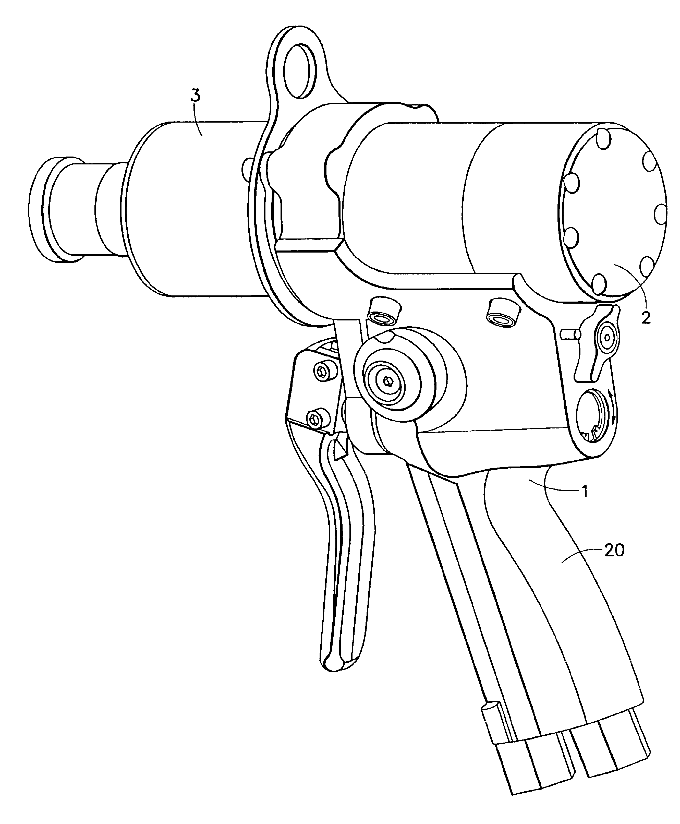
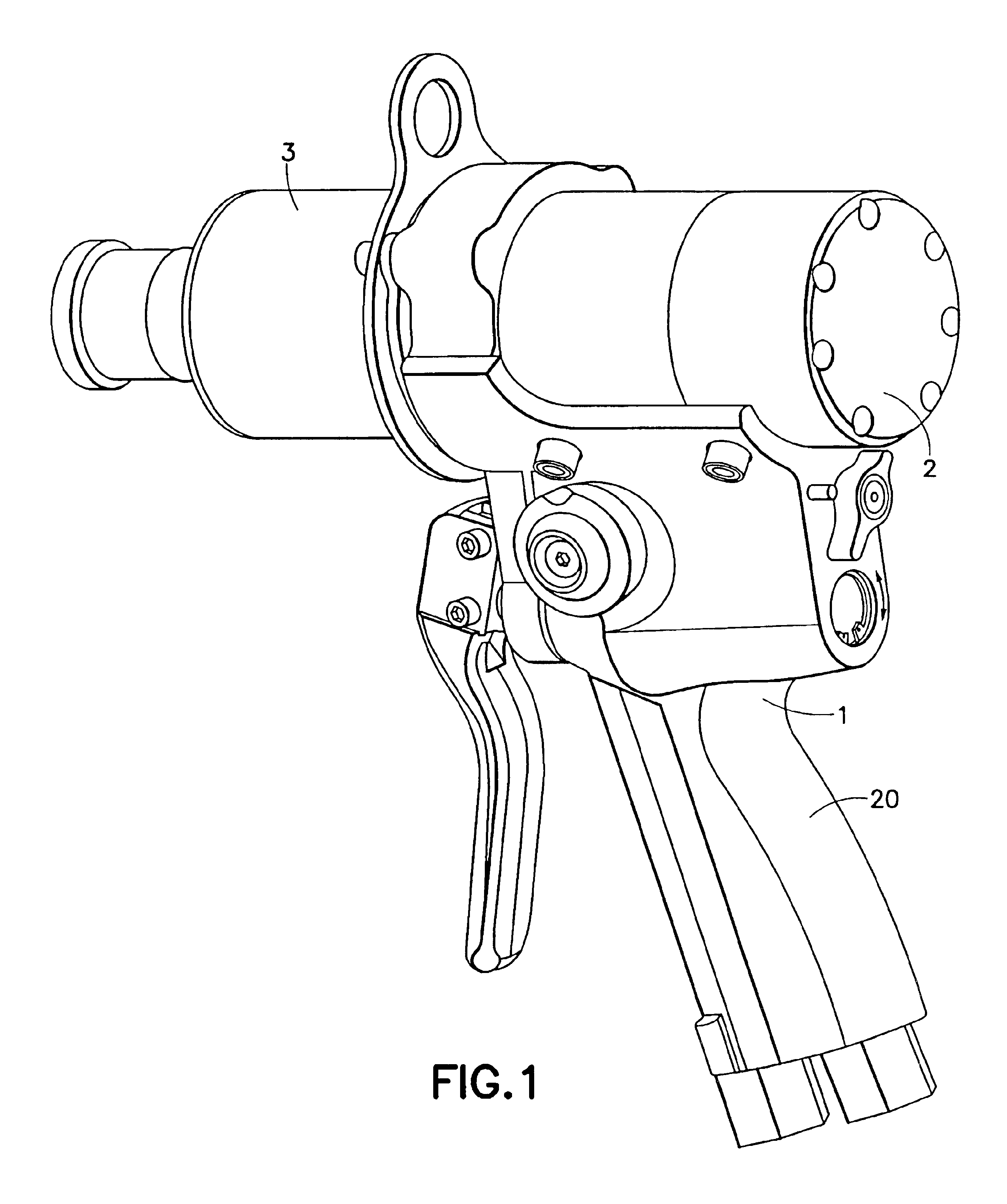
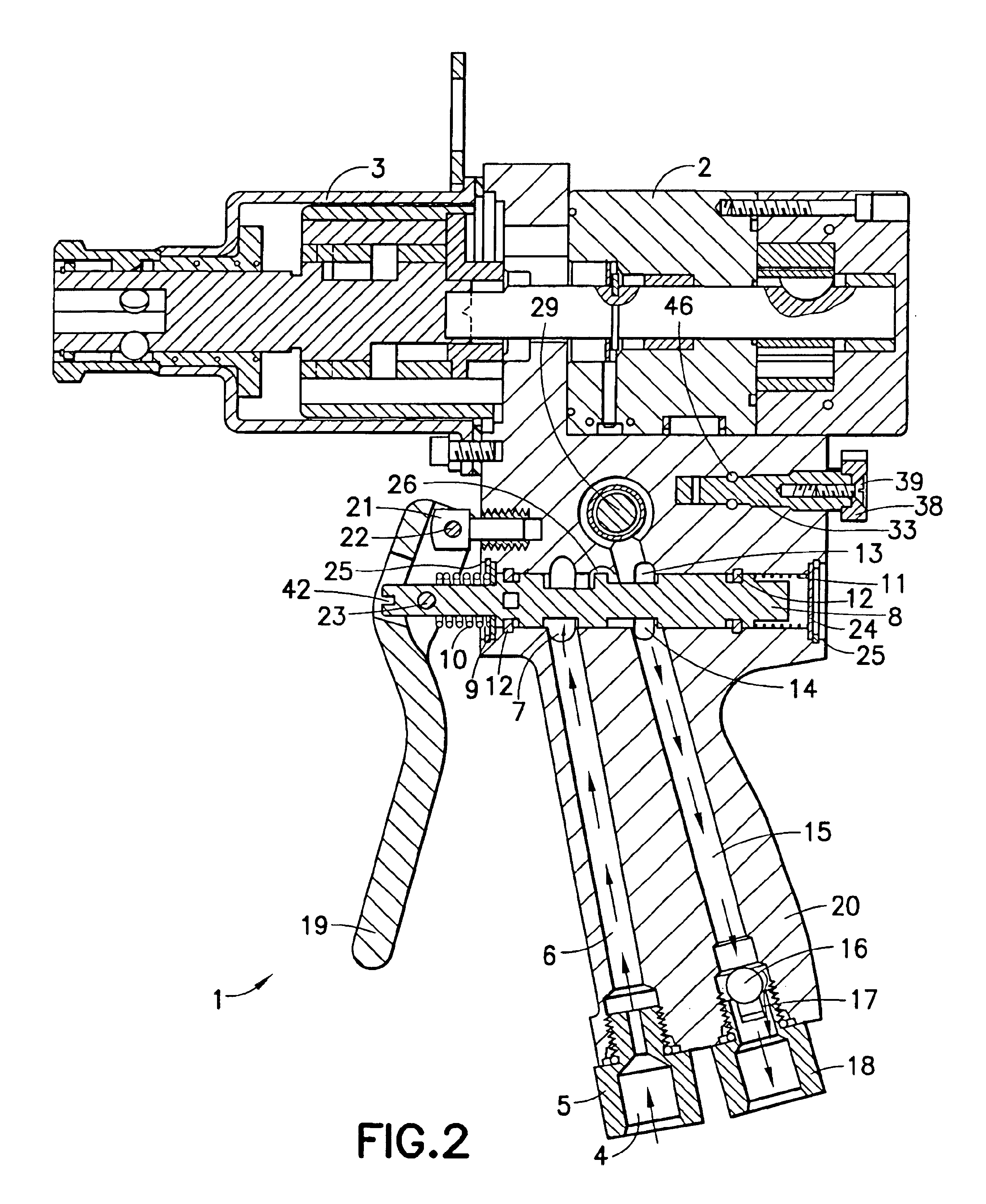
[0026]Disclosed herein are methods and apparatus for providing a fluid control system for a fluid operated tool, wherein the fluid control system provides for variable limitation of power output to the unit performing work. The fluid control system provides multiple flow paths to provide for, among other things, selectable diversion of a portion of flow to a work unit, and reversing the direction of the work unit. Although the work unit is disclosed herein as a gerotor motor (in the preferred embodiment, as a part of a hydraulically driven variable torque impact wrench), it is recognized that the fluid control system may be used with other types of work units contained within other fluid operated tools. These other tools may employ gerotor motors, or other apparatus adapted for fluid drive, such as a gear motor. Examples of other tools include, without limitation: wrenches, grinders, and drills. Therefore, the teachings herein are not limited to a hydraulically driven variable torqu...


PUM

PropertyMeasurementUnit
Fractionaaaaaaaaaa
Fractionaaaaaaaaaa
Fractionaaaaaaaaaa

Abstract

Disclosed herein is a fluid control system for varying the power available to a fluid powered tool, a hydraulically driven impact wrench. The system disclosed herein varies power available to the tool by use of a bypass mechanism that is downstream of a directional control valve spool. Among other things, the advantageous placement of the bypass valve limits the thermal burden in the hydraulic circuit.

Description

TECHNICAL FIELD OF THE INVENTION[0001]This invention relates to improved controls for varying the output power of a liquid driven tool such as a torque wrench.BRIEF DESCRIPTION OF PRIOR DEVELOPMENTS[0002]Certain construction and / or maintenance activities call for powered tools having great output. Hydraulic systems provide certain advantages for powering such tools and are commonly used in some industries.[0003]Consider one task required of utility linemen, that of assembling utility poles, and the equipment thereon. This is typically completed with the pole in an erect position, and by a lineman elevated by a bucket truck. Due to limited space and production demands, versatile tooling that can quickly complete a few tasks is required. For example, the linemen must drill through a utility pole, and preferably without considerable exertion. Experience has shown that hydraulic impact wrenches are a preferred tool for this task. Once drilling has been completed, installation of hardwar...

Claims


Application Information

Patent Timeline
IPC IPC(8): B23B45/00B23B45/04B25B21/02B25B23/145
CPCB25B23/1453B25B21/02
Inventor HALL, JEFFERSON
Owner HUBBELL INC
Why Eureka
Try Eureka