Off-axis reflective optical apparatus

Inactive Publication Date: 2005-06-07
LOCKHEED MARTIN CORP
View PDF6 Cites 10 Cited by
  • Summary
  • Abstract
  • Description
  • Claims
  • Application Information

AI Technical Summary

Benefits of technology

[0008]Embodiments of the present invention are directed to a simple apparatus and a convenient and accurate method of mounting the components to form an off-axis reflective optical apparatus such as a collimator. The invention does so by providing a mounting block having precisely arranged mounting surfaces for the ferrule holder which positions the fiber tip of the optical fiber and for the off-axis optical reflector. The off-axis optical apparatus provides an unobstructed reflected or collimated beam (i.e. with no hole therein) to pass through the exit (or entrance) pupil.

Problems solved by technology

Use of transmissive collimators with lasers with power levels higher than about three kilowatts / m2 becomes increasingly problematic due to limits on energy density that transmissive optic materials can withstand and due to a phenomenon called thermal lending.
The distortion can influence the divergence and mode quality of the beam passing through or reflecting from the optical component and cause detrimental shifts of focus position and diameter.
In addition, focusing or collimating the beam for space or other in-vacuum applications is complicated by the change in the relative index of refraction between vacuum and in-air.
The mounting and alignment of optical components in a reflective collimator, however, can be complicated and can introduce inaccuracies.
Each optic adds complexity to the task of aligning a beam path, is a possible source of beam distortion and absorbs some energy from the beam reducing overall system efficiency.
Optical elements degrade with use.
Each optical element adds to the overall cost of system maintenance.
Existing assemblies utilizing parabolic or other conic reflective surfaces often involve complex packaging, adjustment, alignment, and mounting techniques.
Moreover, on-axis parabolic collimators produce beams that are corrupted by shadows due to the existence of a hole in the center for the exit (or entrance) pupil.
Existing off-axis collimator assemblies are even more complex than on-axis collimator assemblies, and involve additional mounting and alignment components.

Method used


Image

  • Off-axis reflective optical apparatus
  • Off-axis reflective optical apparatus
  • Off-axis reflective optical apparatus

Examples


Embodiment Construction

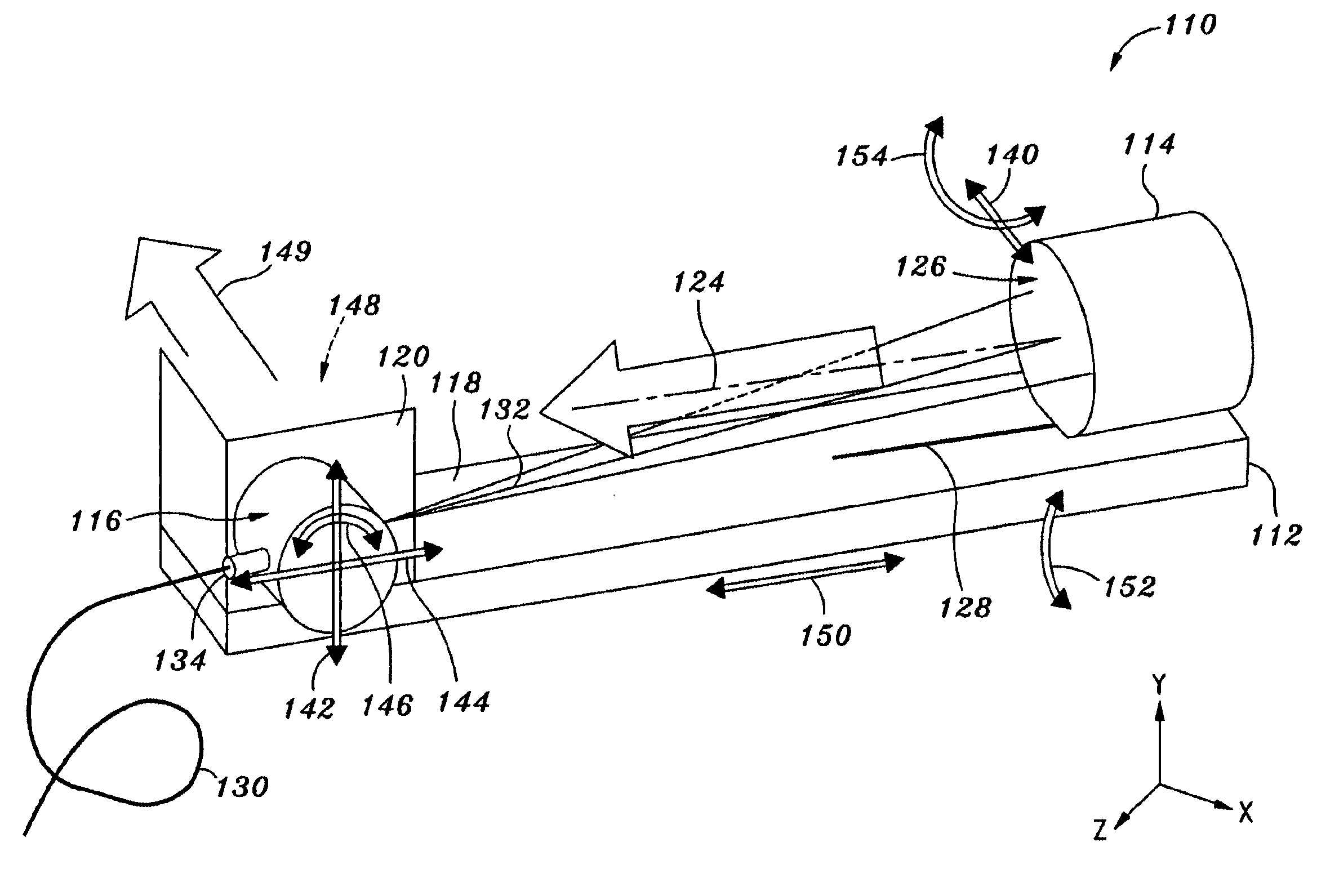
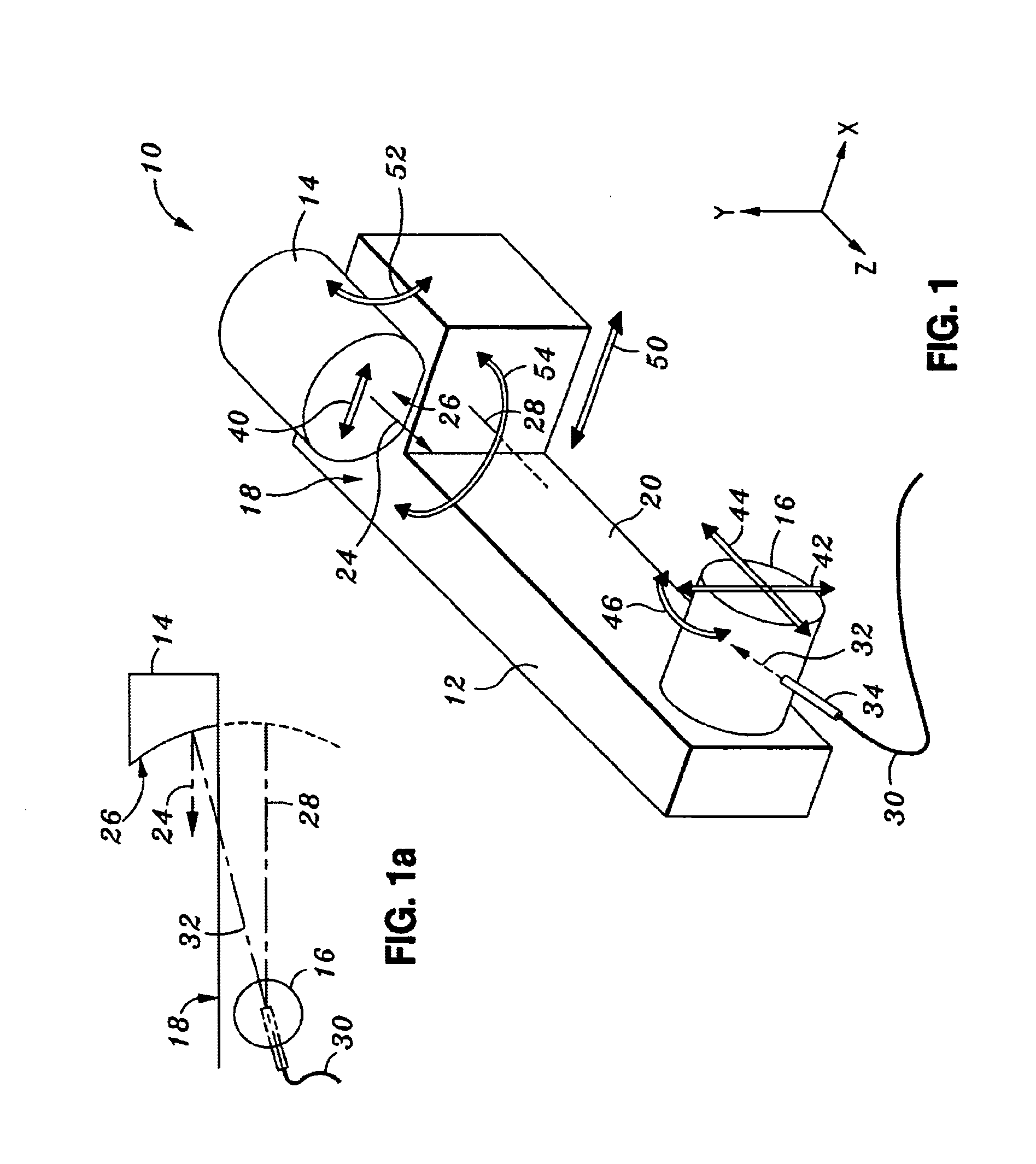
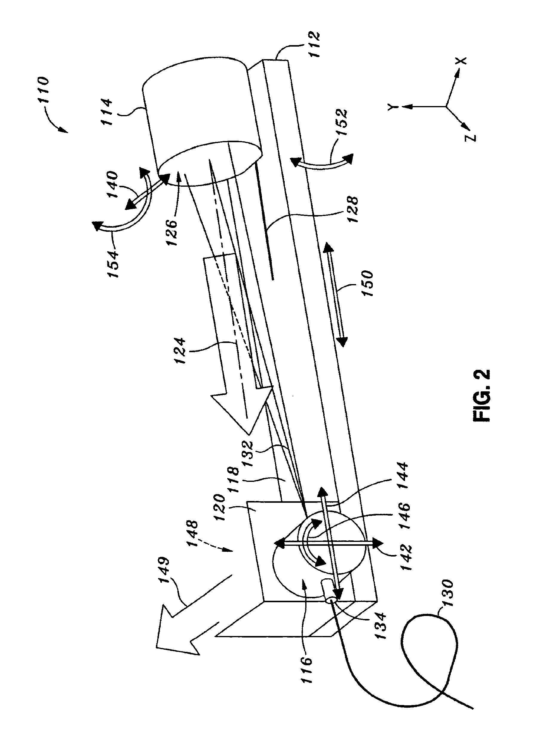
[0016]FIG. 1 shows an off-axis reflective collimator or optical apparatus 10 which includes a mounting block 12 for mounting an optical reflector 14 and a ferrule holder 16. The optical reflector 14 is disposed on an off-axis reflector support surface 18 of the mounting block 12, which is desirably a planar surface. The ferrule holder 16 is disposed on a ferrule holder support surface 20 of the mounting block 12, which is desirably a planar surface. In the embodiment shown, the off-axis reflector support surface 18 is generally perpendicular to the ferrule holder support surface 20.

[0017]The optical reflector 14 has a reflected beam axis or centerline 24 along which a reflected beam will be directed. The reflective surface 26 of the optical reflector 14 is typically a conic reflective surface such as a parabola. The conic reflective surface has a conic center which lies on the reflector axis 28 which passes through the tip of the optical fiber 30 as illustrated in FIG. 1a. The optic...


PUM


Abstract

Embodiments of the present invention are directed to a simple apparatus and a convenient and accurate method of mounting the components to form an off-axis reflective optical apparatus such as a collimator. In one embodiment, an off-axis reflective optical apparatus comprises a mounting block having a ferrule holder support surface and an off-axis reflector support surface which is generally perpendicular to the ferrule holder support surface. An optical reflector is mounted on the off-axis reflector support surface and has a reflected beam centerline. The optical reflector has a conic reflective surface and a conic center. A ferrule holder is mounted on the ferrule holder support surface. The ferrule holder provides a ferrule for coupling to an optical fiber and orienting a fiber tip of the optical fiber along a fiber axis toward the optical reflector. The fiber axis is nonparallel to the reflected beam centerline. Prior to mounting the optical reflector to the off-axis reflector support surface and prior to mounting the ferrule holder to the ferrule holder support surface, the optical reflector is movable on the off-axis reflector surface and the ferrule holder is movable on the ferrule holder support surface to align the conic center of the optical reflector with respect to the fiber tip of the optical fiber, and the apparatus has at least one of the following features: (1) the optical reflector is movable on the off-axis reflector support surface to adjust a focus of the fiber tip with respect to the optical reflector, and (2) the ferrule holder is movable on the ferrule holder support surface to adjust the focus of the fiber tip with respect to the optical reflector.

Description

STATEMENT AS TO RIGHTS TO INVENTIONS MADE UNDER FEDERALLY SPONSORED RESEARCH OR DEVELOPMENT[0001]The invention described herein was made in the performance of work under NASA Contract No. NAS7-1407 and is subject to provisions of Section 305 of the National Aeronautics and Space Act of 1958 (42 U.S.C. 2457).CROSS-REFERENCES TO RELATED APPLICATIONS[0002]NOT APPLICABLEBACKGROUND OF THE INVENTION[0003]The present invention relates generally to optical apparatus and, more particularly, to an off-axis conic reflective optical apparatus such as a collimator.[0004]Collimators are optical devices, belonging to a family of devices known as collimators or telescopes, which include products called beam expanders and condensers. Such devices increase or decrease the size of and change the divergence or angular characteristics of a light beam passed therethrough. Such devices also have other characteristics and functions known to those skilled in the trade. Collimators are used in various applic...

Claims


Application Information

Patent Timeline
IPC IPC(8): G02B6/26G02B6/42
CPCG02B6/262G02B6/4226
Inventor AMES, LAWRENCE L.LEARY, DAVID F.MAMMINI, PAUL V.
Owner LOCKHEED MARTIN CORP
Why Eureka
Try Eureka