High density probe device

a high-density, probe technology, applied in the direction of coupling device connections, instruments, measurement instrument housings, etc., can solve the problems of increasing the complexity and expense of manufacturing and assembling the device, reducing the number of components, and reducing the cost of production. , the effect of facilitating the replacement of spring probes

Inactive Publication Date: 2005-06-07
3M INNOVATIVE PROPERTIES CO
View PDF34 Cites 100 Cited by
  • Summary
  • Abstract
  • Description
  • Claims
  • Application Information

AI Technical Summary

Benefits of technology

[0008]The present invention is a spring probe block assembly for use with automated test equipment. The assembly described and claimed herein provides a cost effective approach for providing both electrically commoned and electrically isolated probes in the probe block assembly. The a spring probe block reduces the number of components used in the completed assembly,

Problems solved by technology

Spring probe block housings are typically machined from metal bar stock in an elaborate and costly sequence of processes that assure precise locations and diameters of the bores that accept press-fitted electrical probes and ground receptacles.
Although generally effective, such a spring probe block construction is expensive and time consuming to produce.
As noted above, the processes required to machine a met

Method used


Image

  • High density probe device
  • High density probe device
  • High density probe device

Examples


Embodiment Construction

[0019]In the following detailed description of the preferred embodiments, reference is made to the accompanying drawings which form a part hereof, and in which is shown by way of illustration specific embodiments in which the invention may be practiced. It is to be understood that other embodiments may be utilized and structural or logical changes may be made without departing from the scope of the present invention. The following detailed description, therefore, is not to be taken in a limiting sense, and the scope of the present invention is defined by the appended claims.

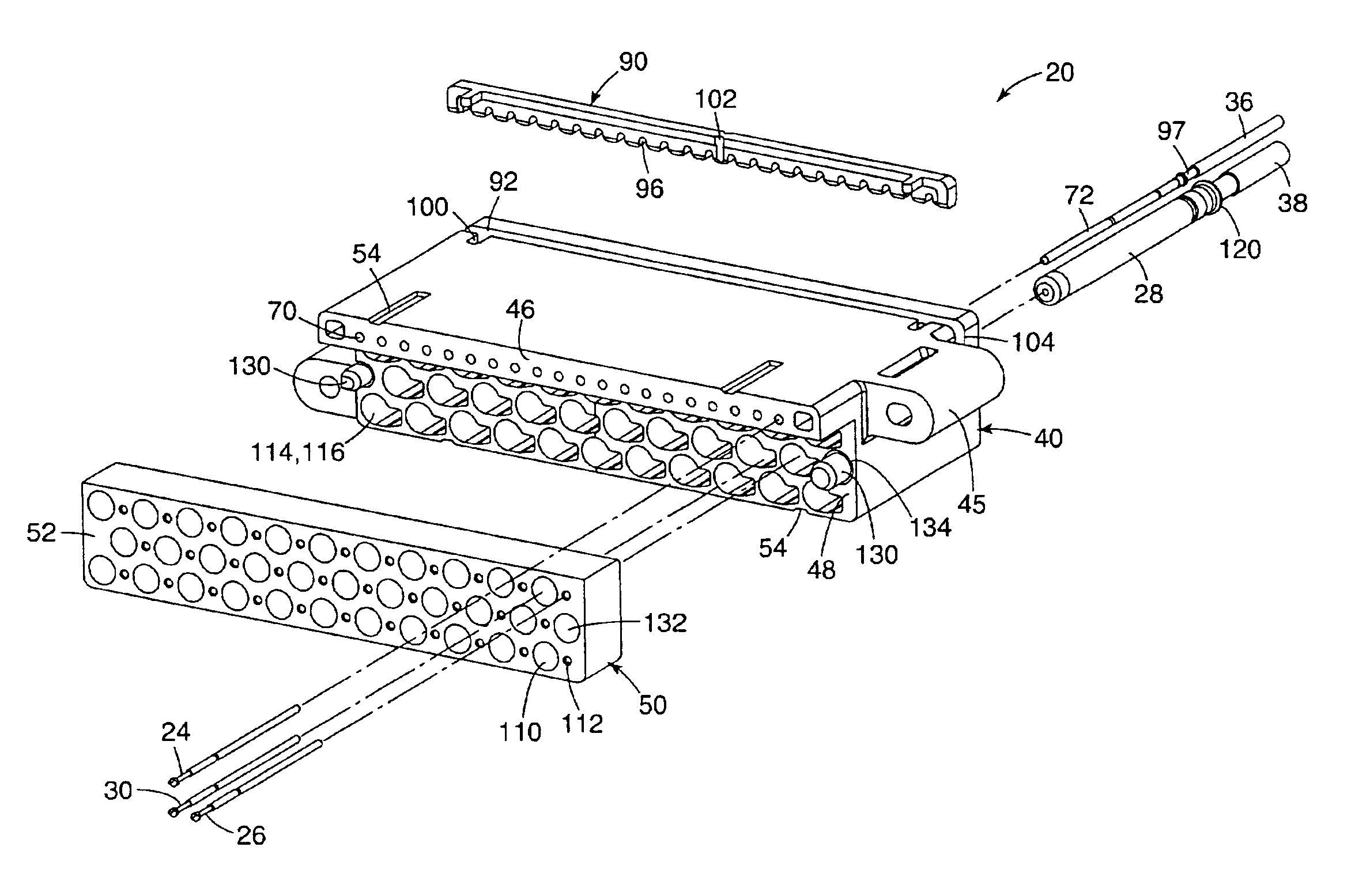
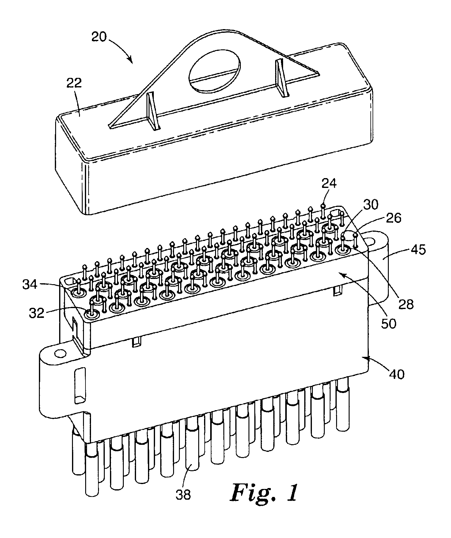
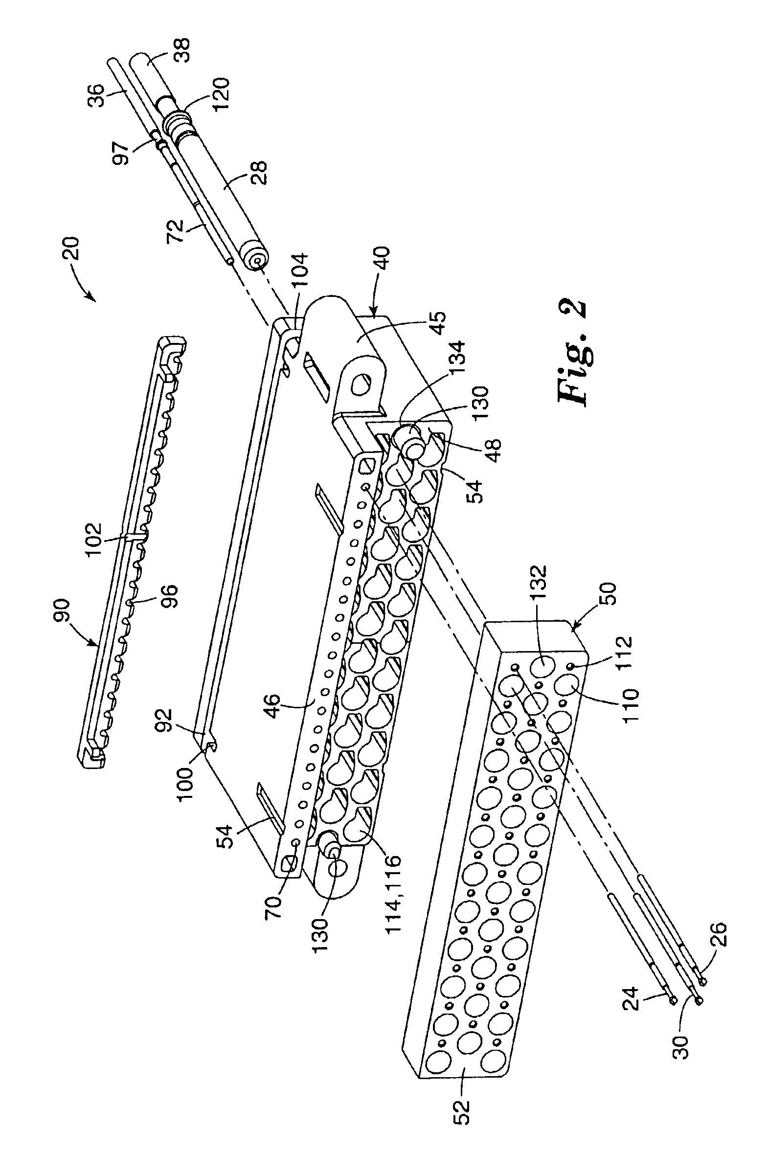
[0020]FIG. 1 provides a perspective view of one embodiment of a spring probe block assembly 20 with a shipping / service cover 22 according to the invention, while FIG. 2 provides an exploded perspective view of the assembly of FIG. 1. As discussed in greater detail below, spring probe block assembly 20 contains a plurality of spring probes, including power or utility spring probes 24, ground spring probes 26, and ...


PUM


Abstract

A probe block assembly has an electrically insulative housing and an electrically conductive plate. The front side of the housing has a forward face and a recessed face. The electrically conductive plate is positioned against the recessed face of the housing. A plurality of probes extend from the forward face of the housing and are electrically isolated from each other and from the conductive plate. A plurality of probes extend from a front surface of the conductive plate and are in electrical contact with each other.

Description

THE FIELD OF THE INVENTION[0001]The present invention relates to spring probe block assemblies of the type used in automatic test equipment (ATE), and specifically to spring probe block assemblies for use in high bandwidth applications.BACKGROUND OF THE INVENTION[0002]Spring probe blocks are used to provide temporary spring contact interfaces between integrated circuits or other electronic equipment and an automated test equipment test head. The automated test equipment performs necessary tests of the integrated circuits or other electronic equipment.[0003]Spring probe block assemblies of the type used in automatic test equipment are widely available and use generally similar designs. Spring probe block housings are typically machined from metal bar stock in an elaborate and costly sequence of processes that assure precise locations and diameters of the bores that accept press-fitted electrical probes and ground receptacles. The solid metal fabrication also serves to commonly ground...

Claims


Application Information

Patent Timeline
IPC IPC(8): G01R1/067G01R1/073G01R1/04G01R1/02
CPCG01R1/07314G01R1/06772G01R1/04B33Y80/00
Inventor FELDMAN, STEVEN
Owner 3M INNOVATIVE PROPERTIES CO
Why Eureka
Try Eureka