Cage plate adjusting mechanism for a bicycle rear derailleur

Inactive Publication Date: 2005-06-07
SHIMANO INC
View PDF12 Cites 19 Cited by
  • Summary
  • Abstract
  • Description
  • Claims
  • Application Information

AI Technical Summary

Benefits of technology

[0011]Another object of the present invention is to provide an adjusting mechanism

Problems solved by technology

Also, due to this looseness, the housing can vibrate on the tubular mem

Method used


Image

  • Cage plate adjusting mechanism for a bicycle rear derailleur
  • Cage plate adjusting mechanism for a bicycle rear derailleur
  • Cage plate adjusting mechanism for a bicycle rear derailleur

Examples


Example

Second Embodiment

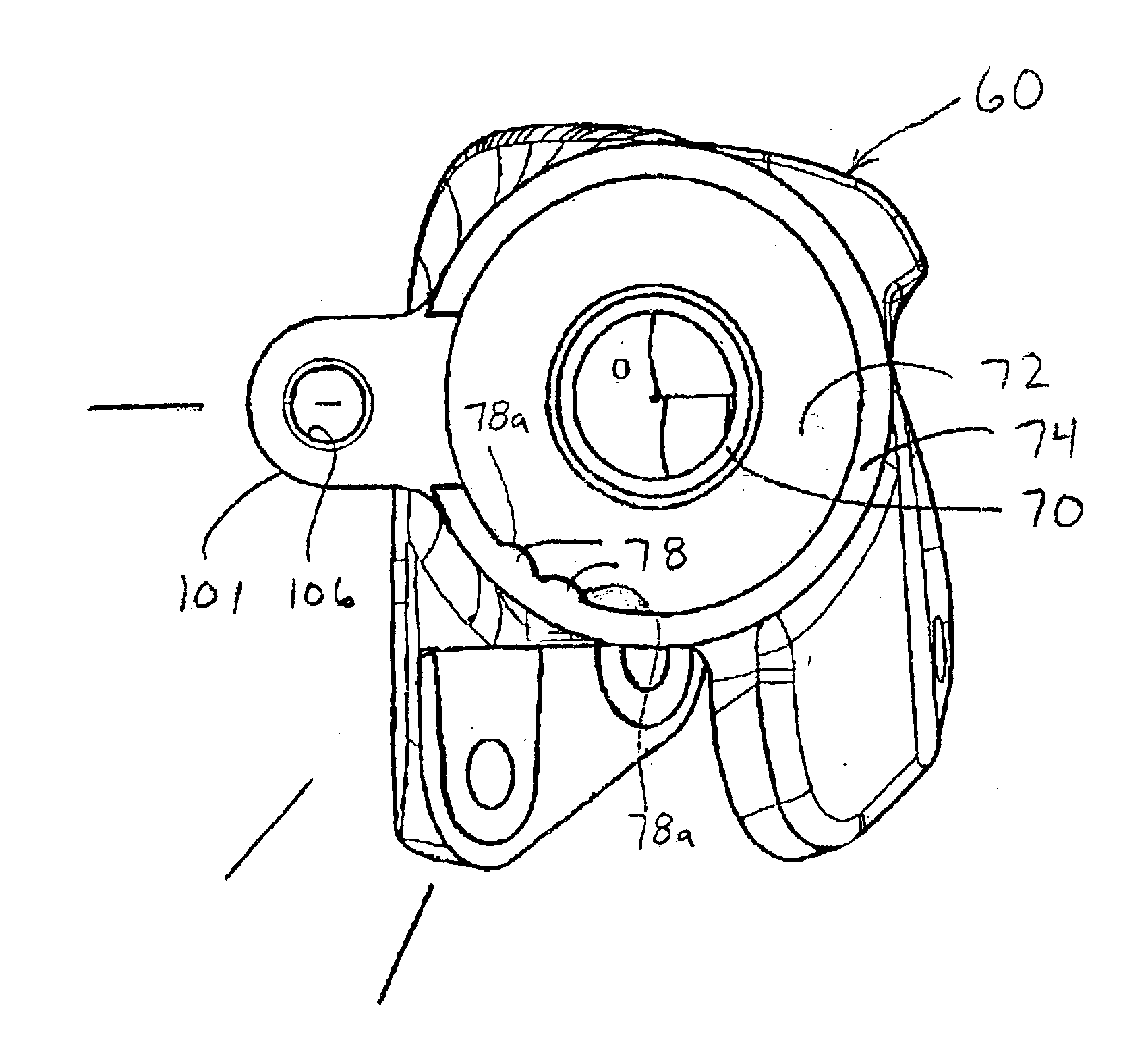
[0090]Referring now to FIG. 28, a portion of a derailleur 10′ is illustrated in accordance with a second embodiment of the present invention. Only the base member 20′ of the derailleur 10′ will be illustrated, since the remainder of the derailleur 10′ is conventional and can be understood by reference to the first embodiment.

[0091]The base member 20′ of the derailleur 10′ is provided with an adjustment mechanism 13′. The adjustment member 13′ is substantially identical to the adjustment member 13 of the first embodiment, but is installed on the base member 20′ instead of the movable member 22. Since the construction of the adjustment mechanism 13′ of the base member 20′ is substantially the same as the adjustment mechanism 13 of the movable member 22 of the first embodiment, this embodiment will not be discussed or illustrated in detail herein. Rather, the following description will focus mainly on the differences. Moreover, in view of these similarities between the...


PUM


Abstract

An adjusting mechanism is provided for a bicycle derailleur, which can adjust a position of a chain guide in an axial direction. The derailleur basically has a base member, a movable member with the chain guide and a linkage assembly. The adjustment mechanism is preferably operatively coupled between the movable member and the chain guide, or between the base member and the frame. The adjusting mechanism includes a first tubular portion, a second tubular portion, a biasing member and an adjustment member. The second tubular portion is arranged around the first tubular portion to move axially relative to the first tubular portion via the adjustment member. The biasing member is arranged to apply an urging force on the tubular portions. One of the tubular portions has a rigid non-compressible support projection arranged to selectively contact the other tubular portion when the tubular portions move relative to each.

Description

BACKGROUND OF THE INVENTION[0001]1. Field of the Invention[0002]This invention generally relates to a rear derailleur for a bicycle. More specifically, the present invention relates to an adjusting mechanism for adjusting the position of the chain guide in an axial direction with respect to a multistage sprocket assembly of the bicycle.[0003]2. Background Information[0004]Bicycling is becoming an increasingly more popular form of recreation as well as a means of transportation. Moreover, bicycling has become a very popular competitive sport for both amateurs and professionals. Whether the bicycle is used for recreation, transportation or competition, the bicycle industry is constantly improving the various components of the bicycle as well as the frame of the bicycle. One component that has been extensively redesigned is the drive train of the bicycle.[0005]Most of today's bicycles are multi-speed bicycles that allow the rider to select the appropriate gear ratio to suit the particu...

Claims


Application Information

Patent Timeline
IPC IPC(8): B62M9/00B62M9/12B62M9/1244B62M9/126
CPCB62M9/1244Y10T403/1616
Inventor FUKUDA, MASAHIKO
Owner SHIMANO INC
Why Eureka
Try Eureka