Stacked OLED display having improved efficiency

a technology of oled display and efficiency, applied in the field of oled color display, can solve the problems of reducing the lifetime or reducing the resolution compared to a prior art three, reducing the efficiency of pixels in the display, and imai design not providing increased power efficiency for emissive full color display, etc., to achieve the effect of improving lifetime and power efficiency and simple construction

Inactive Publication Date: 2005-06-07
GLOBAL OLED TECH
View PDF9 Cites 111 Cited by
  • Summary
  • Abstract
  • Description
  • Claims
  • Application Information

AI Technical Summary

Benefits of technology

[0010]The present invention provides a full color flat panel OLED display

Problems solved by technology

Hence, the design of Siwinski will result in either reduced lifetime or reduced resolution compared to a prior art three element design.
However, such stacked structur

Method used


Image

  • Stacked OLED display having improved efficiency
  • Stacked OLED display having improved efficiency
  • Stacked OLED display having improved efficiency

Examples


Embodiment Construction

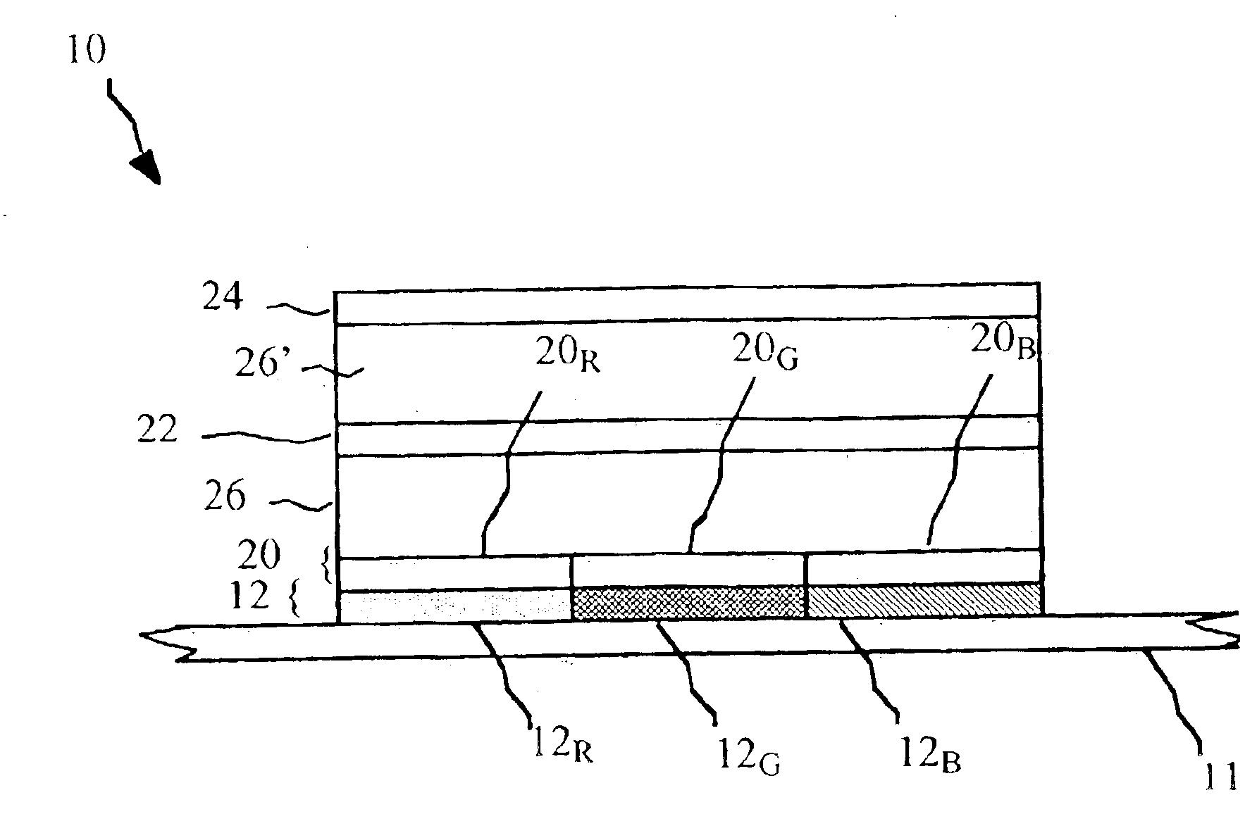
[0020]Referring to FIG. 1, a bottom emitting OLED device according to the present invention includes a color pixel 10 located on a substrate 11 having a filter layer 12 including a plurality of light transmissive filters 12R, 12G, 12B for transmitting red, green and blue light respectively. A first patterned electrode layer 20 defines a corresponding plurality of separately addressable electrodes 20R, 20G and 20B. A first layer of white light emitting OLED material 26 is disposed over electrode layer 20. A second layer of white light emitting OLED material 26′ is electrically connected in series with the first layer through a transparent doped organic conductor layer 22. A second electrode layer 24 defines a single electrode coextensive with the plurality of color filters. First electrode layer 20 is transparent and second electrode layer 24 may be reflective. Transparent electrodes are well known in the art and, for example, may be made of indium tin oxide (ITO) or thin layers of m...


PUM


Abstract

An OLED device having a pixel, including a plurality of light transmissive filters; a first electrode layer defining a corresponding plurality of separately addressable electrodes; a first layer of white light emitting OLED material; a doped organic conductor layer; a second layer of white light emitting OLED material; and a second electrode layer defining a single electrode coextensive with the plurality of color filters.

Description

FIELD OF THE INVENTION[0001]The present invention relates to OLED color displays and, more particularly, to arrangements of light emitting elements in the pixels of such OLED color displays.BACKGROUND OF THE INVENTION[0002]US Patent Application No. 2002 / 0186214A1, by Siwinski, published Dec. 12, 2002, shows a method for saving power in an organic light emitting diode (OLED) display having pixels comprised of red, green, blue and white light emitting elements. The white light emitting elements are more efficient than the other colored light emitting elements and are employed to reduce the power requirements of the display by displaying a black and white image under certain conditions.[0003]OLED devices age as current passes through the emissive materials of the display. Specifically, the emissive materials age in direct proportion to the current density passing through the materials. Hence, the solution proposed by Siwinski will have the effect of either reducing the size of the emis...

Claims


Application Information

Patent Timeline
IPC IPC(8): H01L27/15H01L33/00H01L51/10H01L51/05H01L27/32H01L51/50H01L51/52
CPCH01L27/3213H01L51/5278H01L27/322H01L51/5036G09G3/3208G09G2300/0426G09G2300/023H10K59/351H10K59/38H10K50/125H10K50/19H10K59/30
Inventor COK, RONALD S.
Owner GLOBAL OLED TECH
Why Eureka
Try Eureka