
Gain flattened bi-directionally pumped Raman amplifier for WDM transmission systems

a raman amplifier and gain flattened technology, applied in the field of optical communication systems, can solve the problems of limited bandwidth of edfa technology, degrade osnr performance, and utility, and achieve excellent gain flatness and large bandwidth

Inactive Publication Date: 2005-06-07
CISCO TECH INC
View PDF10 Cites 30 Cited by
  • Summary
  • Abstract
  • Description
  • Claims
  • Application Information

AI Technical Summary

Benefits of technology

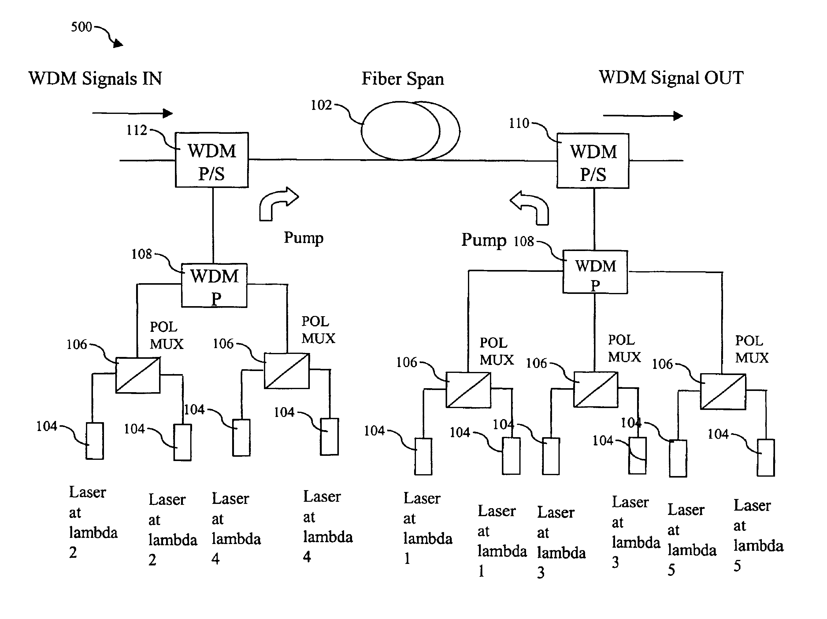
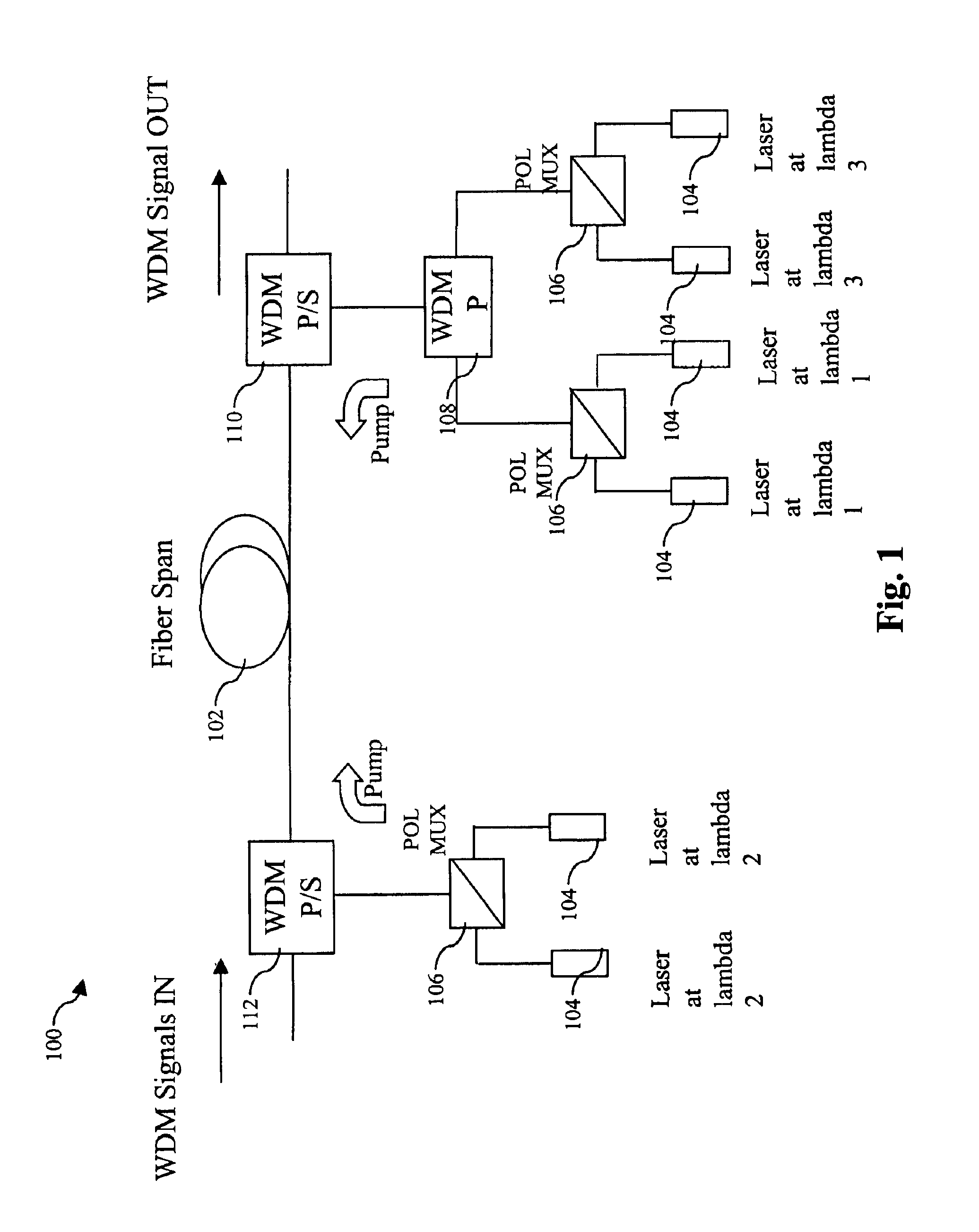
[0009]By virtue of one embodiment of the present invention, Raman amplification of a WDM signal with excellent gain flatness across a very large bandwidth is achieved. Co-propagating and counter-propagating Raman pumping are combined in the same fiber. Multiple pumping wavelengths are employed. Wavelengths employed for co-propagating pumping and wavelengths employed for counter-propagating pumping alternate in order of wavelength. In one embodiment, N co-propagating pump wavelengths and N+1 counter-propagating pump wavelengths are used. Alternatively, one may use N+1 co-propagating pump wavelengths and N counter-propagating pump wavelengths.

Problems solved by technology

The enormous growth in Internet traffic is challenging the telecommunication industry to develop technology that will greatly expand the available bandwidth of backbone communication networks.
One of the principal limitations of EDFA technology is limited bandwidth.
Flat gain can be provided by the use of gain flattening filters (GFFs) but their utility is limited due to their insertion loss which degrades OSNR performance.
The degradation of OSNR detrimentally reduces the span length that may be achieved without optical amplification and the link length that may be achieved without regeneration of the optical signal from recovered data.
However, even using this technique, further increases in the desired bandwidth of the WDM signal to accommodate increases in data traffic cannot be achieved without the detrimental addition of a gain-flattening filter.

Method used


Image

  • Gain flattened bi-directionally pumped Raman amplifier for WDM transmission systems
  • Gain flattened bi-directionally pumped Raman amplifier for WDM transmission systems
  • Gain flattened bi-directionally pumped Raman amplifier for WDM transmission systems

Examples


Embodiment Construction

[0021]One embodiment of the present invention is directed towards a Raman amplification system having many beneficial characteristics including, e.g., excellent gain flatness and excellent OSNR. Representative applications include DWDM transmission systems, DWDM receiver systems, and mid-line amplification in DWDM links. For example, the disclosed Raman amplification systems may be applied to DWDM communication links that carry an optical signal over 2500 km without regeneration of the optical signal from recovered data. In one embodiment, as many as 140 or more WDM channels spaced e.g., 25 GHz or less apart may be accommodated over such ultra-long distances.

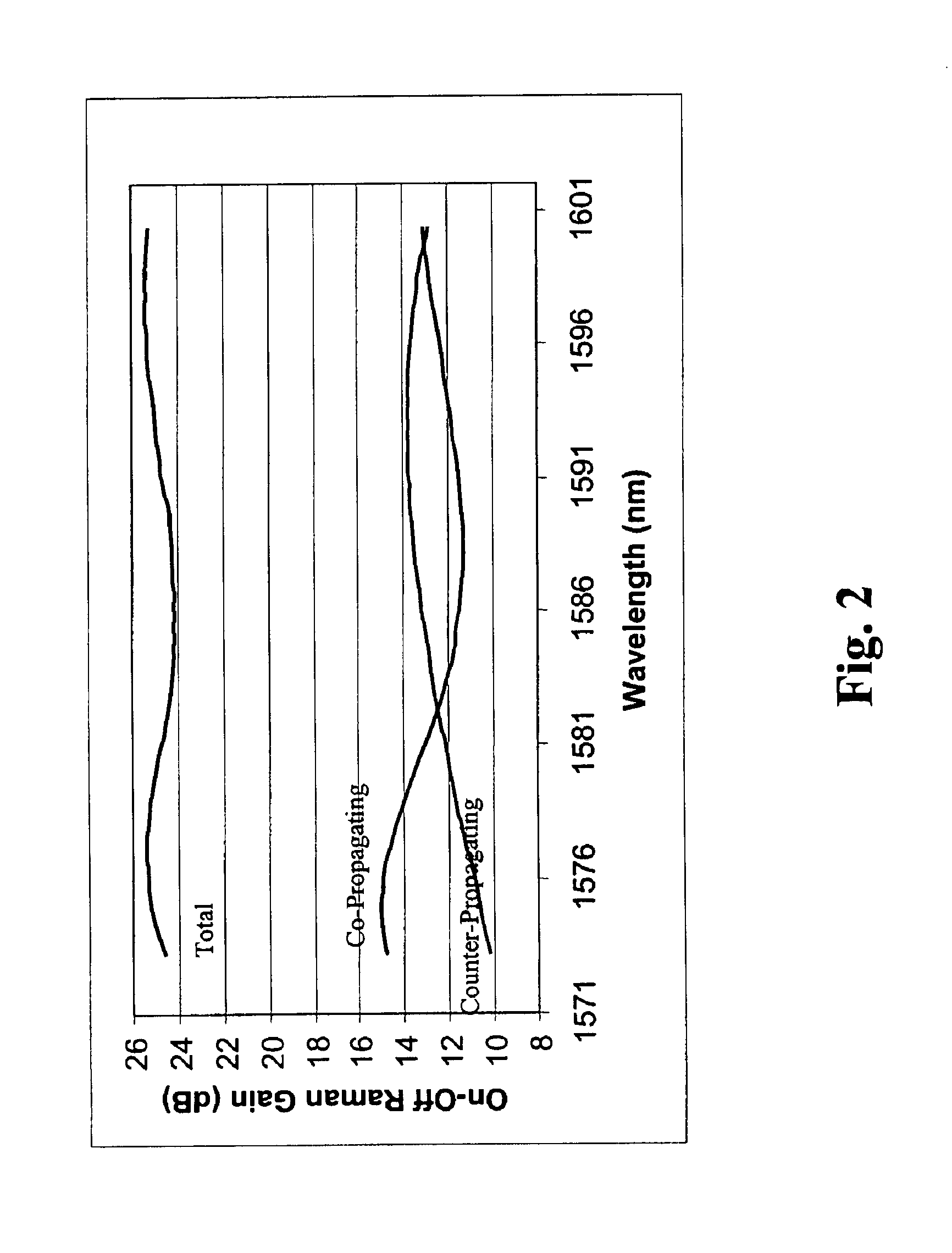
[0022]One embodiment of the present invention provides a Raman amplification scheme that exploits a combination of counter-propagating Raman pumping and co-propagating Raman pumping as disclosed in U.S. patent application Ser. No. 09 / 899,872. About half of the total on-off gain is provided by co-propagating Raman pumping. The us...


PUM


Abstract

Raman amplification of a WDM signal with excellent gain flatness across a very large bandwidth is achieved. Co-propagating and counter-propagating Raman pumping are combined in the same fiber. Multiple pumping wavelengths are employed. Wavelengths employed for co-propagating pumping and wavelengths employed for counter-propagating pumping alternate in order of wavelength. In one embodiment, N co-propagating pump wavelengths and N+1 counter-propagating pump wavelengths are used. Alternatively, one may use N+1 co-propagating pump wavelengths and N counter-propagating pump wavelengths.

Description

STATEMENT OF RELATED APPLICATIONS[0001]The present invention is related to the subject matter of U.S. Patent App. Ser. No. 09 / 899,872, entitled “Reduced Four-Wave Mixing Raman Amplification Architecture,” filed on Jul. 5, 2001, the contents of which are herein incorporated by reference in their entirety for all purposes.BACKGROUND OF THE INVENTION[0002]The present invention relates to optical communication systems, and more particularly to amplification in optical communication systems.[0003]The enormous growth in Internet traffic is challenging the telecommunication industry to develop technology that will greatly expand the available bandwidth of backbone communication networks. Further improvements in optical communication technology hold great promise to meet continuing demands for greater and greater bandwidth.[0004]Wavelength Division Multiplexing (WDM) technology, in particular dense WDM (DWDM) techniques, permit the concurrent transmission of multiple channels over a common ...

Claims


Application Information

Patent Timeline
IPC IPC(8): H01S3/00H01S3/067H01S3/094H01S3/30H04B10/17
CPCH01S3/06754H04B10/294H01S3/302H04B10/2916H01S3/094011H01S3/094096
Inventor CARNIEL, FEDERICODI PASQUALE, FABRIZIOBRAVERMAN, ADA LIVIA
Owner CISCO TECH INC
Learn More