Apparatus and method for flattening gain profile of an optical amplifier

a gain profile and optical amplifier technology, applied in the field of optical fiber amplifiers, can solve the problems of light prone to lose power, effective limits the amount of optical amplifiers a transmission link, variation of signal load at the input of the amplifier, etc., and achieve the effect of increasing the flatness of the gain profil

Active Publication Date: 2011-06-28
LUMENTUM OPERATIONS LLC
View PDF15 Cites 5 Cited by
  • Summary
  • Abstract
  • Description
  • Claims
  • Application Information

AI Technical Summary

Benefits of technology

[0029]wherein the functions f1 . . . fM and F1 . . . FN are chosen so as to increase the flatness of the gain profile G(λ).

Problems solved by technology

While propagating through the optical fiber, light tends to lose power due to the losses related to the physics of how the light interacts with the optical fiber.
Unfortunately, during the amplification process some amount of noise is introduced into the optical signal which effectively limits the amount of optical amplifiers a transmission link can have.
Reconfiguration of the optical communication system leads to variation of the signal load at the input of the amplifier.
At the same time, the goal of the amplifier is to provide constant gain, which should not depend on the power or wavelength loading condition; otherwise, some channels will not have sufficient power and signal-to-noise level at the receiver end, resulting in information being lost.
Hence even if the average gain of an EDFA is held constant, the gain of the individual channels will vary, leading to undesirable effects, such as increased bit error rate of the transmission system.
First, because the DGE and OCM are expensive components, they are not generally installed at each amplifier node, thus they compensate several amplifiers at once, which is not optimal.
Second, both OCM and DGE are comparatively slow devices, and thus the correction usually takes a few seconds.
This is undesirable for agile communication systems where a typical requirement for the adjustment for a transient event such as a change of the channel load is on the order of 100 μs, which is 10,000 times shorter than for a DGE / OCM approach.
The main disadvantage of this technique is the requirement of the constant presence of those three channels the power of which is constantly monitored.
This is a very limiting requirement for modern agile communication systems.
Another potential disadvantage is the requirement to have three additional detectors.
One disadvantage of this approach is that only one control parameter, specifically the EDFA gain, is adjusted which limits the degree to which both the SHB and SRS can be compensated.
Another disadvantage stems from the fact that certain load change patterns, for example the patterns which leave the total optical power measured in a single spectral band unchanged, will not be detected by the apparatus of Nishihara et al. and therefore will not be compensated for by said apparatus.

Method used


Image

  • Apparatus and method for flattening gain profile of an optical amplifier
  • Apparatus and method for flattening gain profile of an optical amplifier
  • Apparatus and method for flattening gain profile of an optical amplifier

Examples


Embodiment Construction

[0038]While the present teachings are described in conjunction with various embodiments and examples, it is not intended that the present teachings be limited to such embodiments. On the contrary, the present teachings encompass various alternatives, modifications and equivalents, as will be appreciated by those of skill in the art.

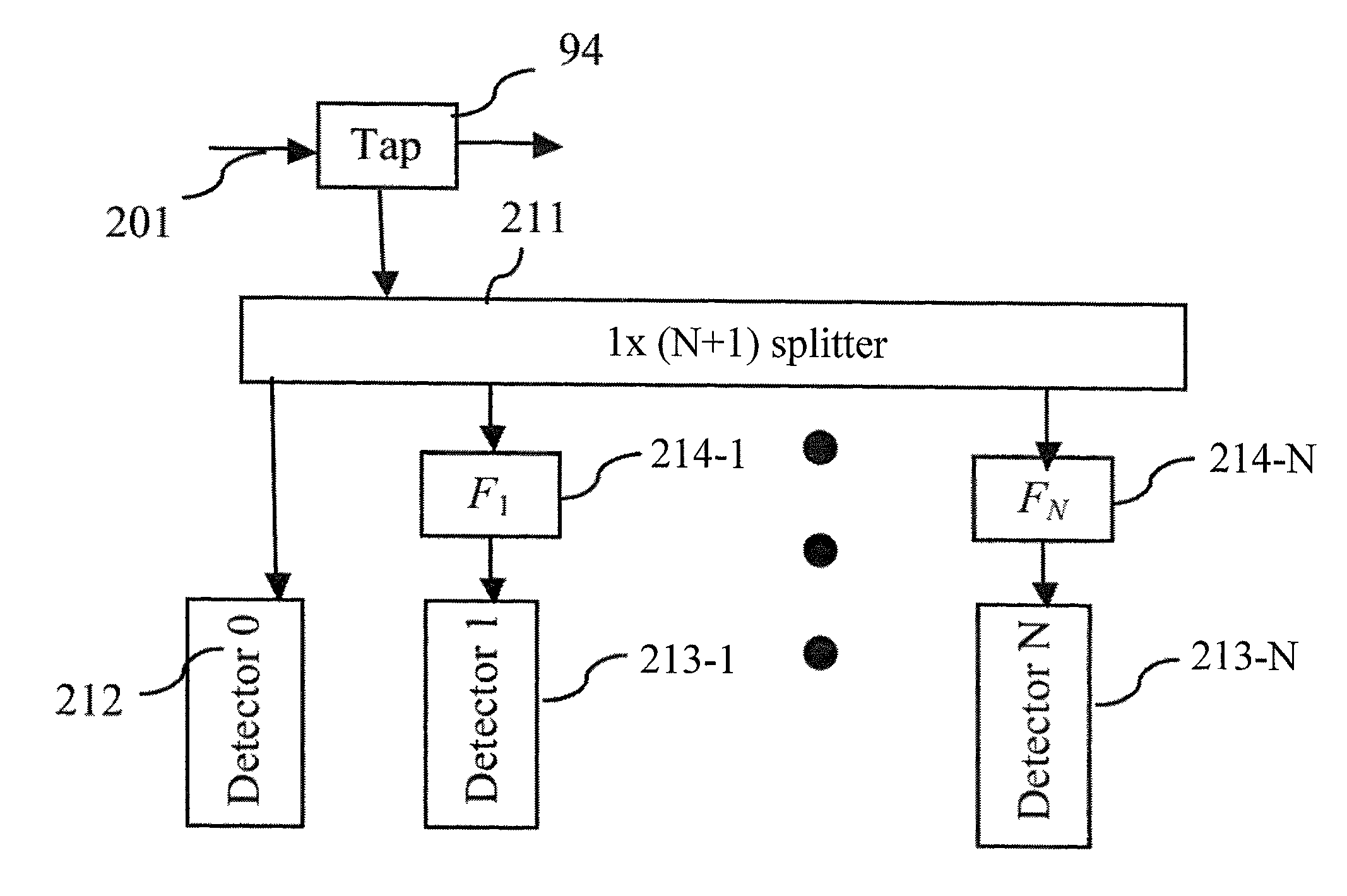
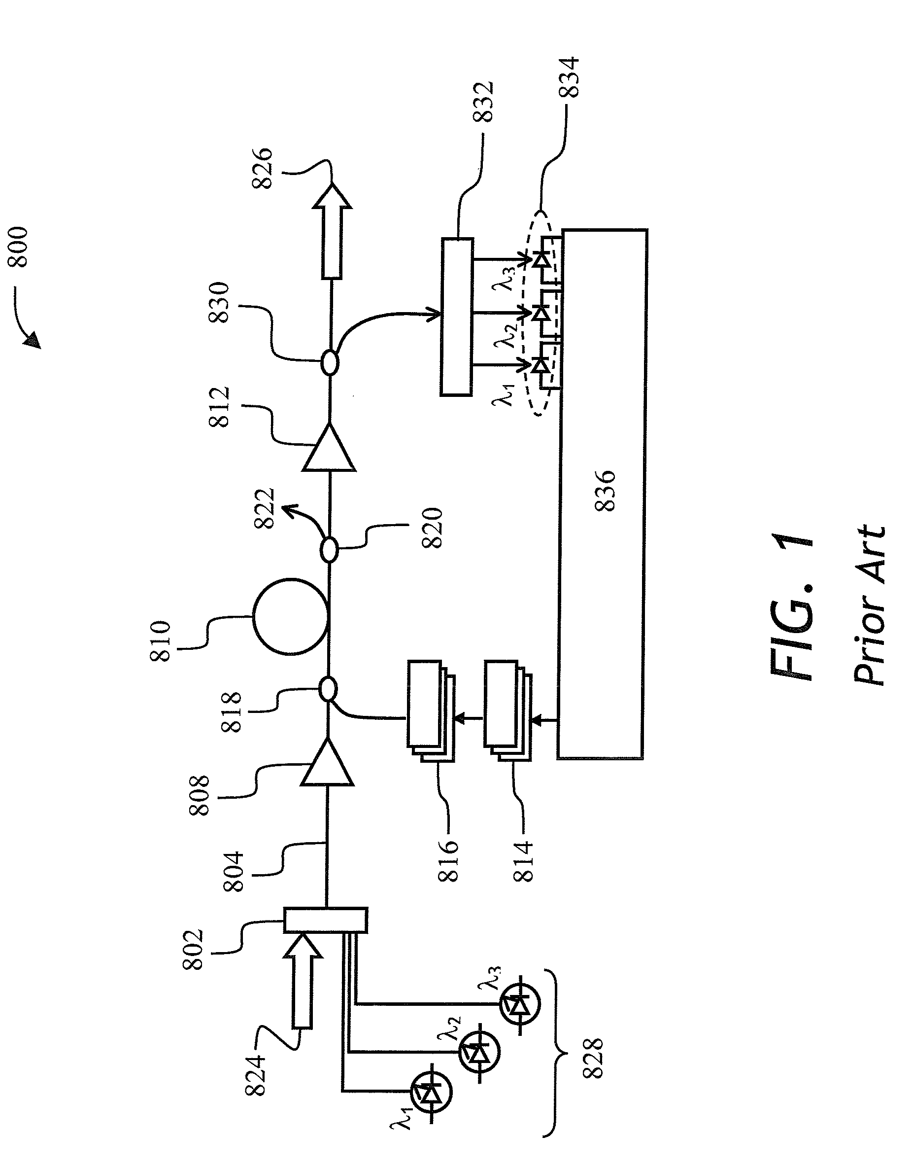
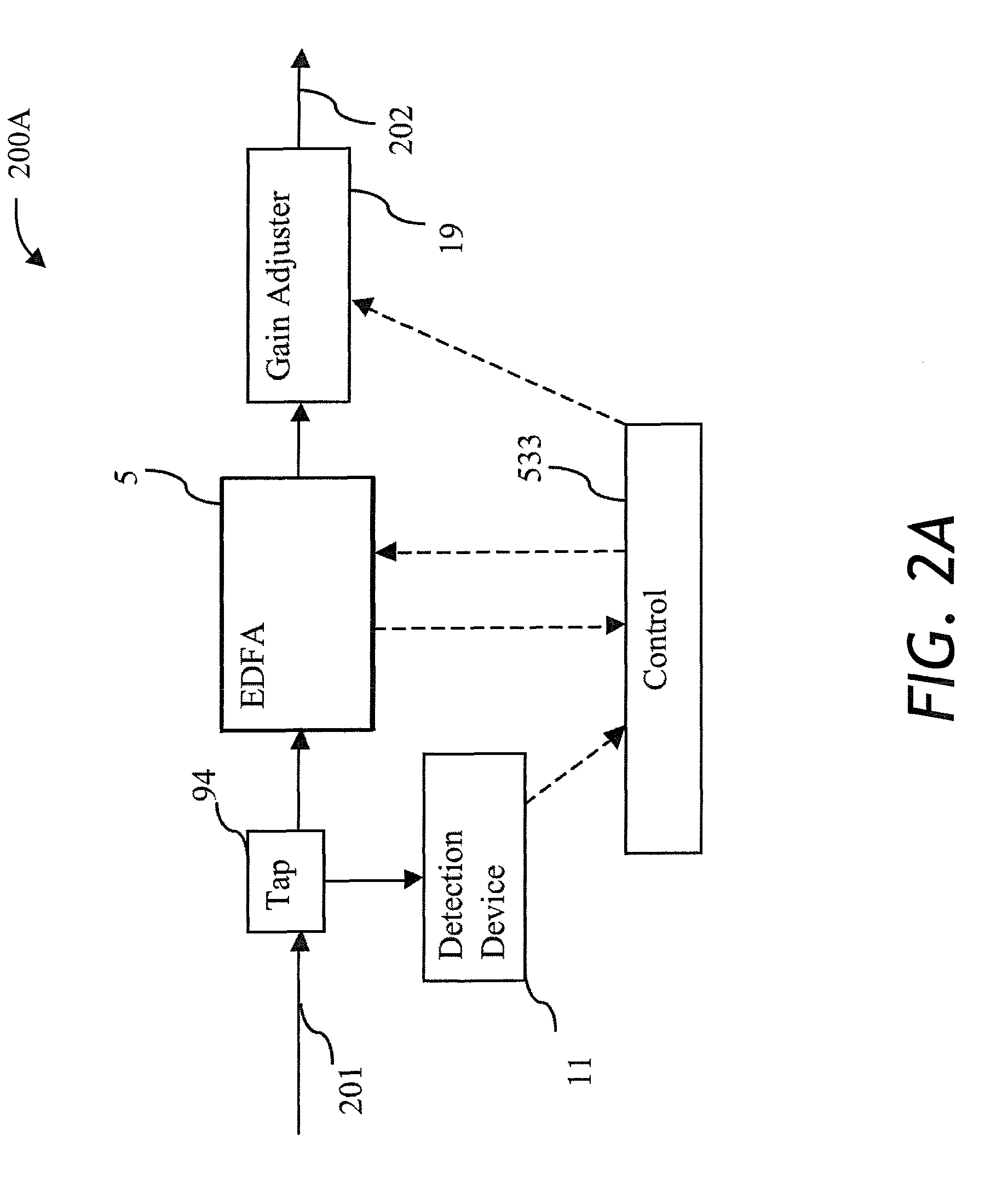
[0039]Referring to FIG. 1, a prior art hybrid optical amplifier 800 is shown comprising a multiplexor 802, a first erbium doped fiber amplifier (EDFA) 808, a span of dispersion compensated optical fiber (DCF) 810, a second EDFA 812, three Raman pump diode lasers 816 emitting pump light at differing pump wavelengths, a Raman pump in-coupler 818 for coupling the Raman pump to DCF 810, and a Raman pump out-coupler 820 for removing a residual Raman pump light 822. An incoming multi-wavelength signal 824, carried by many optical fibers, is multiplexed by multiplexor 802 to propagate in a single optical fiber 804 coupled to amplifier 808. After amplification by...


PUM


Abstract

A change in loading conditions of fiber amplifiers in an optical communications network causes rapid variations in the gain profile of the amplifiers due to spectral hole burning and stimulated Raman scattering. An apparatus for reducing such gain profile variations is described which monitors optical signal perturbations and reacts by adjusting pump powers of the amplifiers and, or fast variable optical attenuator according to a pre-determined function stored in the form of constants in controller's memory. The optical signal is monitored as total power, and the power of light after passing through one or more optical filters. The light detection is relatively fast, whereby the gain profile variations are compensated by fast controlled variable optical attenuator and pump power adjustment upon the change in loading conditions.

Description

CROSS-REFERENCE TO RELATED APPLICATIONS[0001]The present invention claims priority from U.S. provisional patent application No. 60 / 978,253, filed Oct. 8, 2007, which is incorporated herein by reference.TECHNICAL FIELD[0002]The present invention is related to optical fiber amplifiers, and in particular to flattening the gain profile of erbium doped fiber amplifiers (EDFA), Raman Amplifiers (RA), and hybrid EDFA-RA amplifiers.BACKGROUND OF THE INVENTION[0003]In a wavelength division multiplexing optical transmission system, various information channels are encoded into light at different wavelengths, which is combined using a multiplexor. The combined light is transmitted through an optical fiber and, or an optical fiber network to a receiver end of the optical fiber. At the receiver end, the signal is separated, or demultiplexed, back into the individual optical channels through a de-multiplexor, whereby each optical channel can be detected by an optical detector such as a photodiode...

Claims


Application Information

Patent Timeline
Patent Type & Authority Patents(United States)
IPC IPC(8): H04B10/17H01S3/30H04B10/12
CPCH01S3/1301H04B10/296H01S3/06754H01S3/10015H01S3/302H01S2301/04H01S3/2375H01S3/13013
Inventor BOLSHTYANSKY, MAXIMCOWLE, GREGORY
Owner LUMENTUM OPERATIONS LLC
Why Eureka
Try Eureka