Magnetic head including magnetoresistive element for perpendicular magnetic recording type disk drive

a magnetic head and perpendicular magnetic technology, applied in the field of perpendicular magnetic recording type disk drives, can solve the problems of never generated problem, distorted read signal waveform from the read head element, etc., and achieve the effect of preventing and suppressing the saturation of the gmr element and high-quality read signal

Inactive Publication Date: 2005-06-07
KK TOSHIBA
View PDF9 Cites 7 Cited by
  • Summary
  • Abstract
  • Description
  • Claims
  • Application Information

AI Technical Summary

Benefits of technology

[0011]The object of the present invention is preventing and suppressing of the saturation of the GMR element, providing perpendicu

Problems solved by technology

When a recording signal recorded magnetically in a perpendicular direction to a disk surface is reproduced by means of this conventional GMR element, there may occur such a problem that saturation phenomenon of the GMR element occurs so that a read signal waveform from the read head element is distorted.
Because according to the longitudinal magnetic recording method, magnetic field applied from such uniformly magnetized region to the GMR element is substantially

Method used


Image

  • Magnetic head including magnetoresistive element for perpendicular magnetic recording type disk drive
  • Magnetic head including magnetoresistive element for perpendicular magnetic recording type disk drive
  • Magnetic head including magnetoresistive element for perpendicular magnetic recording type disk drive

Examples


first modification

(First Modification)

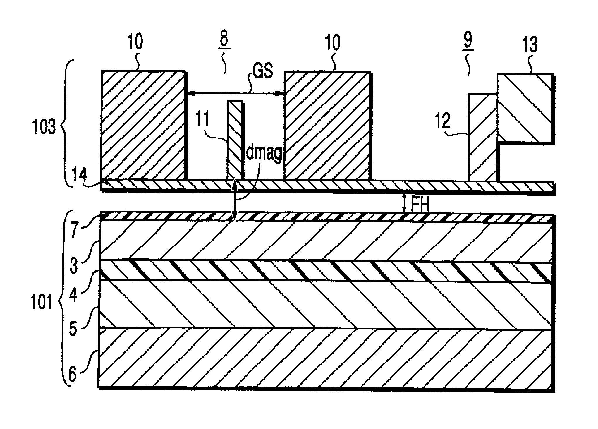
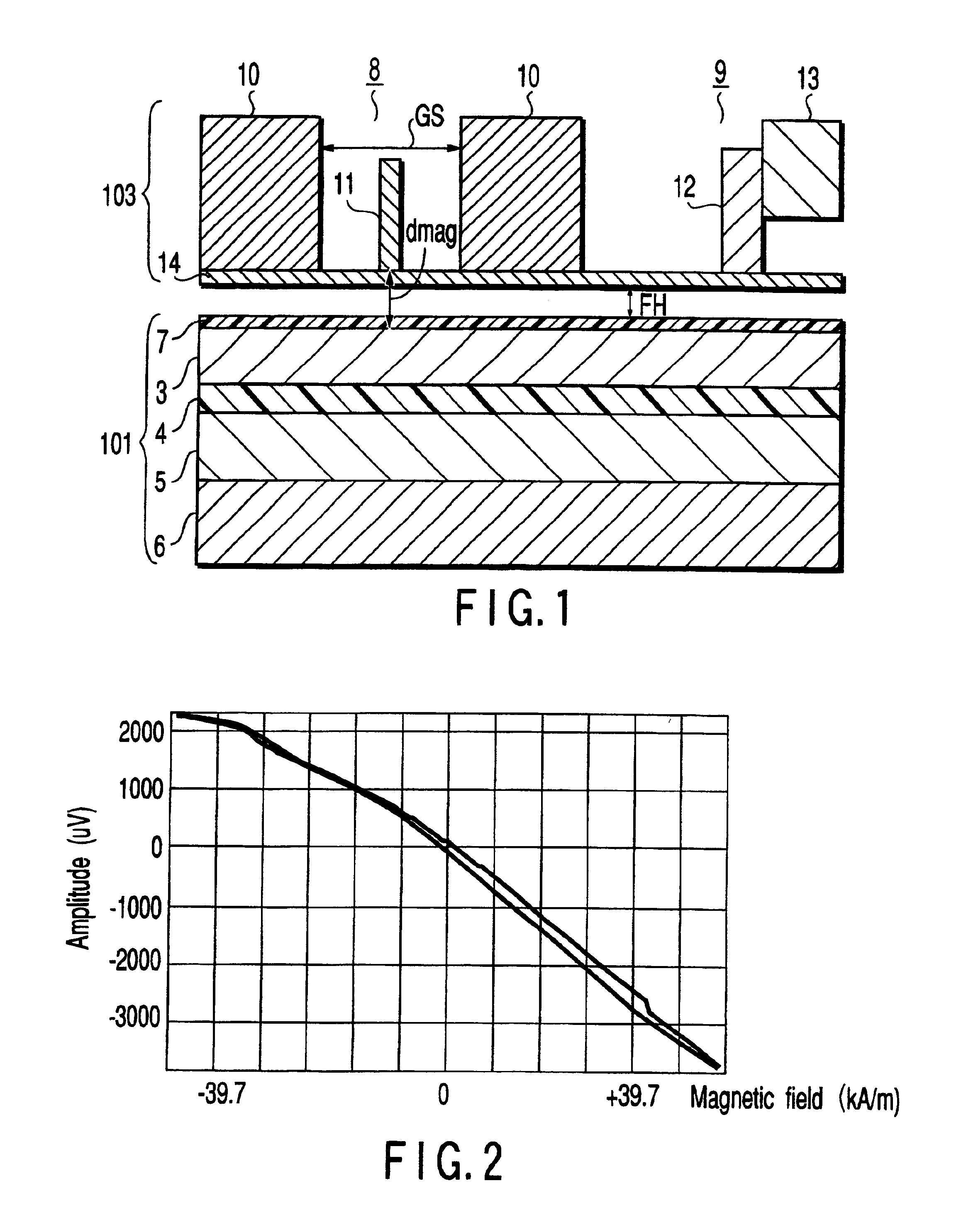
[0049]According to this modification, a GMR element employing a specular / artificial exchange coupling type spin-valve element is applied as the GMR element 11. The structure of the read head element 8 using the GMR element 11 is basically the same as the embodiment shown in FIG. 1.

[0050]The GMR element 11 of this modification has a film structure of PtMn / CoFe / Ru / NiFe / CoFe / Cu / CoFe / NiFe / CeFeO / Ta. Its shield interval, that is, the shield gap length (Gs) is, for example, about 100 nm. The height (H) in the vertical direction of the GMR element is, for example, about 300 nm. The artificial exchange coupling magnetic field (Hex) is, for example, about 158.8 (kA / m).

[0051]As described above, the write head 9 has a perpendicular single-pole type recording magnetic pole 12 opposing the disk 101. Further, the write head 9 has a yoke 13 disposed behind the recording magnetic pole 12 such that it is electrically connected to the recording magnetic pole 12. The write head 9 i...

second modification

(Second Modification)

[0056]FIG. 7 is a diagram showing the second modification of the same embodiment.

[0057]FIG. 7 is a sectional view of a GMR element 20 and a perpendicular magnetic recording type disk 21 seen in the direction of the track width. The GMR element 20 comprises a GMR magnetic sensor portion 22 and hard magnetic film 24 for applying longitudinal bias magnetic field 23 to the GMR magnetic sensor portion 22, provided on both end portions. The hard magnetic film 24 has a function for generating bias magnetic field which produces a uniform magnetization state (29) parallel to the disk surface in the free layer of the GMR magnetic sensor portion 22.

[0058]The disk 21 includes a recording magnetic layer 25 having perpendicular anisotropy, soft magnetic layer 26 provided under this layer as a backing layer and hard magnetic layer 27. This hard magnetic film 27 is exchange-coupled with an interface of the soft magnetic layer 26 in order to suppress generation of a magnetic wal...


PUM


Abstract

This invention provides a perpendicular magnetic recording type disk drive comprised of a double-layered disk medium and a magnetic head containing a read head element containing a GMR element. The GMR element has a linear response dynamic range characteristic larger than an average value of a reproduction magnetic field from a disk 101 and a characteristic capable of avoiding or suppressing saturation phenomenon even if it is affected by a strong reproduction magnetic field from the disk medium.

Description

CROSS-REFERENCE TO RELATED APPLICATIONS[0001]This application is based upon and claims the benefit of priority from the prior Japanese Patent Application No. 2000-396017, filed Dec. 26, 2000, the entire contents of which are incorporated herein by reference.BACKGROUND OF THE INVENTION[0002]1. Field of the Invention[0003]The present invention relates to generally a perpendicular magnetic recording type disk drive and more particularly to a disk drive composed of a double-layered perpendicular magnetic recording type disk medium and a read head including an MR element.[0004]2. Description of the Related Art[0005]In recent years, public attention has been paid to a perpendicular magnetic recording as a technology for surpassing the limit of recording density of conventional longitudinal magnetic recording in the field of a disk drive represented by the hard disk drive. In this field of the perpendicular magnetic recording system, a disk drive which employs a double-layered disk medium ...

Claims


Application Information

Patent Timeline
IPC IPC(8): G11B5/127G11B5/02G11B5/012G11B5/03G11B5/00G11B5/82G11B5/667G11B5/39G11B5/65G11B5/66
CPCG11B5/012G11B5/02G11B5/03G11B5/1278G11B2005/0029G11B5/82G11B2005/0008G11B2005/0016
Inventor TANAKA, YOICHIRO
Owner KK TOSHIBA
Why Eureka
Try Eureka