Electrical drive for a vehicle

a technology of electric drive and vehicle, which is applied in the direction of electric propulsion mounting, electric devices, brake systems, etc., can solve the problems and achieve the effect of saving both weight and space in the vehicl

Inactive Publication Date: 2005-06-14
GASOLINEIAM NAT BERHAD +1
View PDF19 Cites 23 Cited by
  • Summary
  • Abstract
  • Description
  • Claims
  • Application Information

AI Technical Summary

Benefits of technology

[0010]The invention has the advantage that the electric motor of the electric drive is also used to actuate the wheel brake. The wheel brake requires no electric motor of its own. This saves both weight and space in the vehicle. Another advantage of the invention is that a braking torque of the wheel brake of the electric drive is independent of the rotary speed of the wheel and thus of the speed of the vehicle. Moreover, braking down to a stop is possible, as is a parking brake function. Independently of this, it is also possible with the electric drive of the invention to operate the electric motor as a generator for braking the vehicle, in order to charge a battery, at least if the wheel brake is not actuated. Another advantage of the invention is that the electric motor rotates while the vehicle is in motion, and to actuate the wheel brake there is accordingly no need to accelerate from a stop first; hence the actuation of the wheel brake can be accomplished very quickly, with virtually no time lag.
[0011]In one feature of the invention, the torque-transmitting device has a distributor gear with a gear input, which is drivable by the electric motor, and with at least two gear outputs. The vehicle wheel is connected to and drivable by one of the gear outputs, and with a further gear output the wheel brake is actuatable; that is, its rotation / translation conversion gear, for instance, can be driven to rotate in order to press a friction brake lining against and lift the lining away from a brake body. The two gear outputs are drivable selectively with the gear input, or in other words are shiftable.
[0012]For disconnecting the gear outputs in accordance with a feature of the invention, a disconnector, such as a shiftable coupling is provided. This may be either a frictional- or positive-engagement coupling.
[0013]In another feature of the invention, the torque-transmitting device has a differential gear, such as a planetary gear with which a distribution of the torque of the electric motor to the vehicle wheel and the wheel brake is possible with an intrinsically arbitrary ratio; it is also possible for solely the vehicle wheel to be driven or solely for the wheel brake to be actuated. This feature of the invention has the advantage that it is not only either the vehicle wheel that is driven or the wheel brake that is actuated, but rather that both are simultaneously possible. As a result, in the generator mode, the electric motor can be used for braking the vehicle wheel, and at the same time the wheel brake can be actuated. Another advantage of this feature of the invention is that in the event of a current failure, the wheel brake can be actuated by the rotating vehicle wheel via the differential gear.
[0014]In a further feature of the invention, a shiftable rotational direction reversal on the order of a reverse gear is provided. This has the advantage that to move the vehicle in reverse and / or to release the wheel brake, the direction of rotation of the electric motor need not be reversed.
[0015]Another feature of the invention provides a hydraulic pump which is drivable by the electric motor and with which a hydraulic motor can be driven for driving the vehicle wheel. This feature of the invention also has a hydraulically actuatable wheel brake, that is, for instance a conventional, hydraulically actuatable disk brake caliper, which for the actuation is supplied hydraulically with energy from the hydraulic pump. The actuation of the wheel brake can for instance be done with magnet valves, in the manner known from so-called electrohydraulic brakes. This feature of the invention has the advantage of being very flexible in distributing hydraulic energy from the hydraulic pump to the driven vehicle wheel or wheels and the hydraulically actuatable wheel brake or brakes, and in the case of an adjustable hydraulic pump and / or an adjustable hydraulic motor, it is quite flexible in boosting the torque from the electric motor to the hydraulic motor that drives the vehicle wheel and for a possible reversal of the direction of rotation.

Problems solved by technology

This saves both weight and space in the vehicle.

Method used


Image

  • Electrical drive for a vehicle
  • Electrical drive for a vehicle
  • Electrical drive for a vehicle

Examples


Embodiment Construction

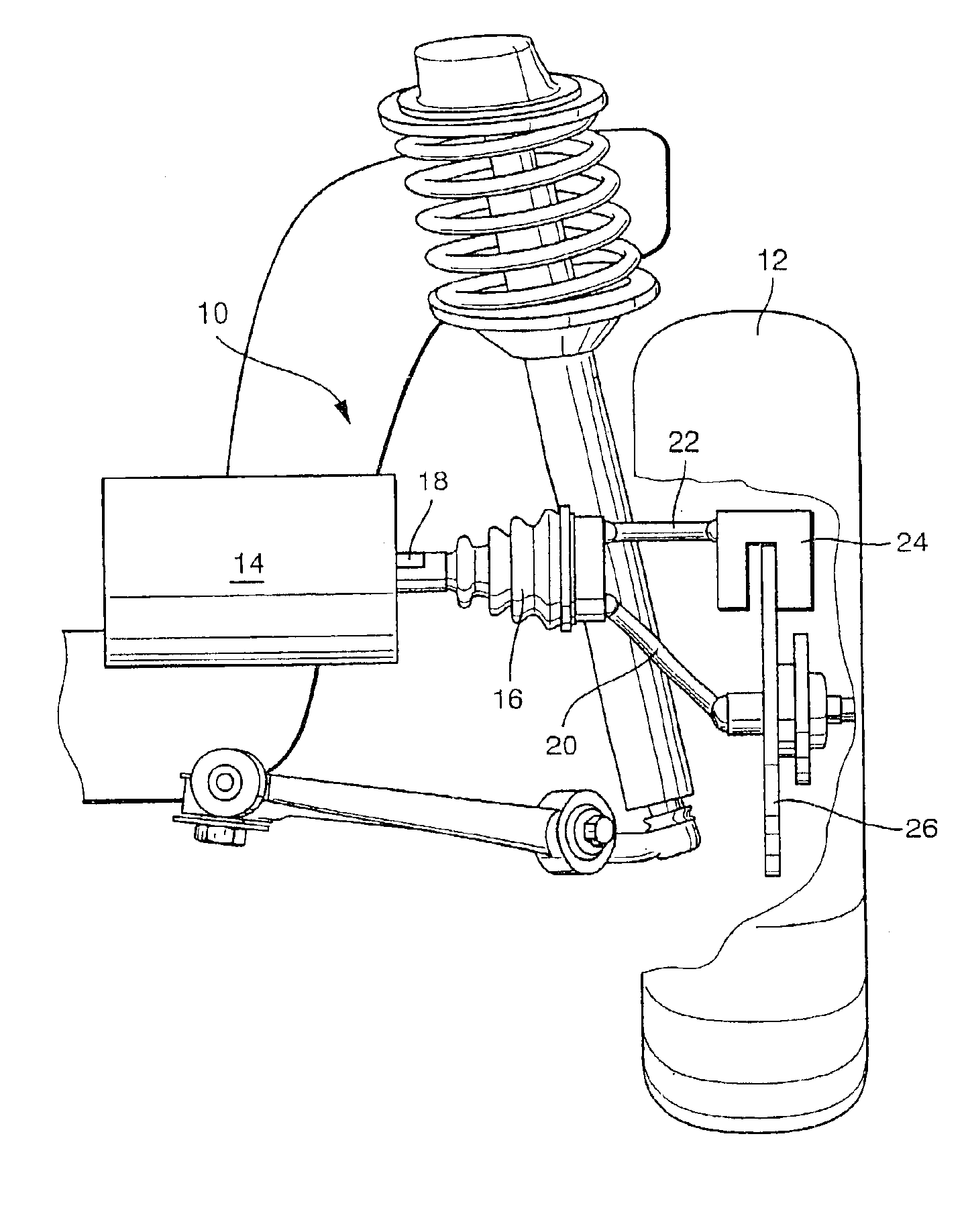
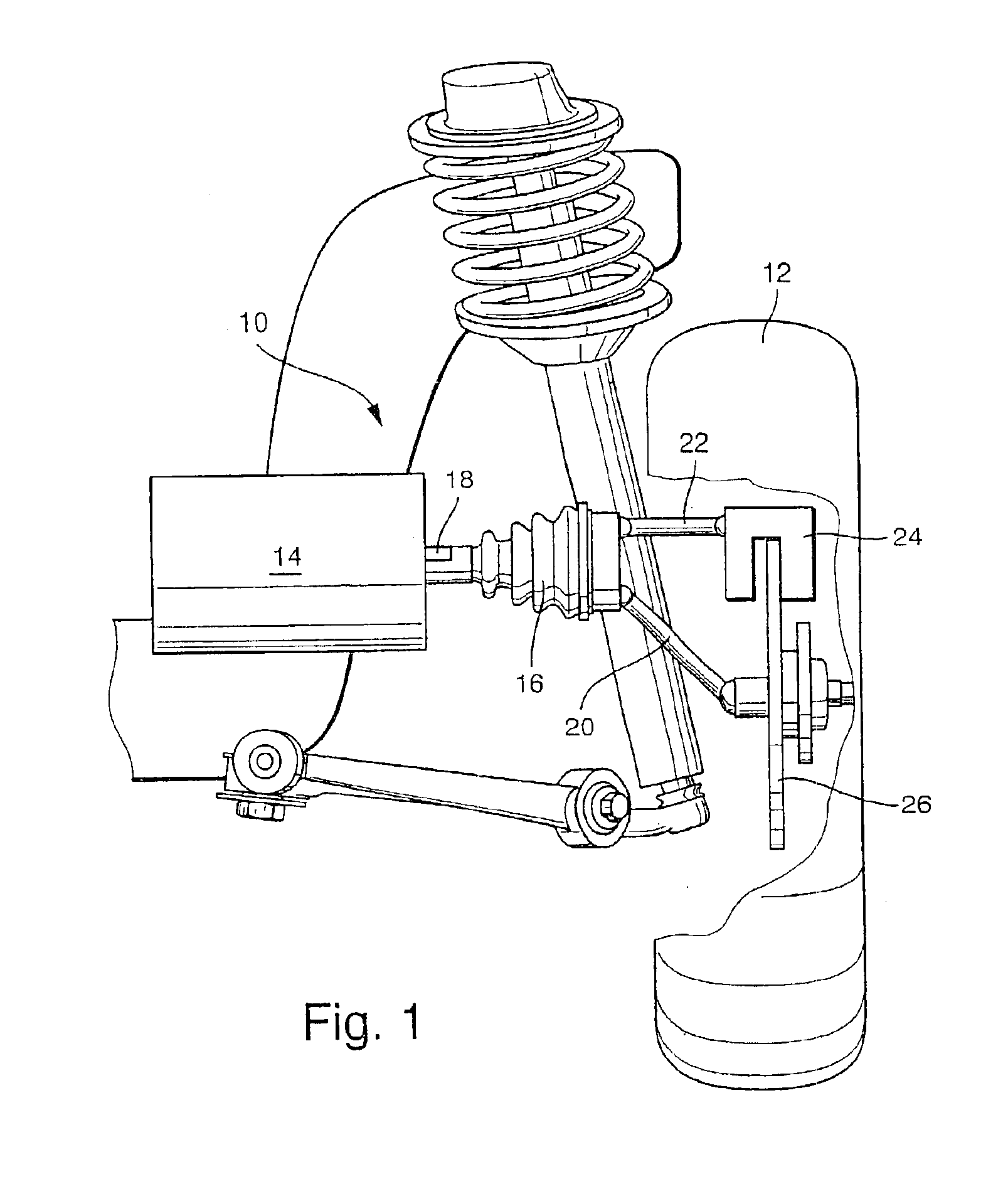
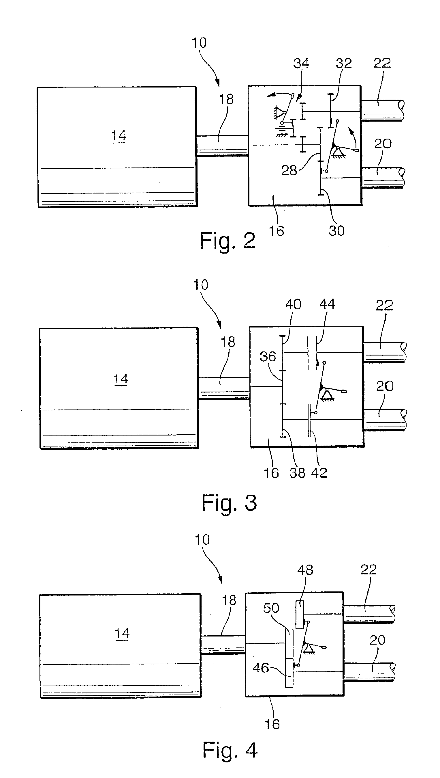
[0019]The electric drive 10 according to the invention, shown in FIG. 1, for a vehicle wheel 12 has an electric motor 14, which is mounted securely to the body of the vehicle. Mounted on the motor 14 is a gear 16, as a torque-transmitting device 16, with a gear input 18 and two gear outputs 20, 22. The gear input 18 is drivable by the electric motor 14. With one gear output 20, via an articulated shaft also identified by reference numeral 20, the vehicle wheel 12 can be driven. Instead of just the vehicle wheel 12, in some embodiments of the invention a wheel brake 24 is selectively actuatable as well, simultaneously with the drive of the vehicle wheel 12. The wheel brake 24 is embodied as a mechanically actuatable disk brake. Wheel brakes 24 of this kind are known per se to one skilled in the art, and since the wheel brake 24 itself is not the subject of the invention, its structure need not be described in further detail here. As one example of a possible design for wheel brake 24...


PUM


Abstract

An electric drive for an electric or hybrid vehicle has an electric motor, with which a vehicle wheel is drivable, for instance via an articulated shaft. The the electric drive is embodied additionally with a mechanically actuatable wheel brake, which is actuatable by the electric motor selectively for driving the vehicle wheel via a shiftable distributor gear. The invention has the advantage that the electric motor provided for driving the vehicle wheel is simultaneously used for actuating the wheel brake (24) as well.

Description

CROSS-REFERENCE TO RELATED APPLICATIONS[0001]This application is a 35 U.S.C. 371 application of PCT / DE00 / 04460, filed on Dec. 14, 2000.BACKGROUND OF THE INVENTION[0002]1. Field of the Invention[0003]The invention relates to an electric drive for a vehicle having a torque-transmitting device for transmitting torque from an electric motor to a vehicle wheel.[0004]2. Description of the Prior Art[0005]Electric drives are known, per se, for use especially in electric or hybrid vehicles and are supplied with electrical energy by a battery (actually an accumulator) or a fuel cell. In city driving, a hybrid vehicle uses the electric drive, for instance, producing no exhaust gas, while on the highway it uses an internal combustion engine that simultaneously recharges the battery.[0006]The known electric drives, for instance in accordance with French Patent Disclosure FR 2 663 591 A, have an electric motor and a torque-transmitting device, for instance a gear, with which a torque of the elect...

Claims


Application Information

Patent Timeline
Patent Type & Authority Patents(United States)
IPC IPC(8): B60K7/00B60K17/04B60K17/10B60T13/74B60T13/00B60K17/22B60K17/14B60L7/24B60T1/06B60W10/10B60W10/12B60W10/18
CPCB60K7/0007B60K17/043B60K17/046B60K17/10B60T13/741B60K2007/0046B60K2007/0061B60L2220/46B60K17/22
Inventor HAAS, HARDYFAYE, IANVOLLERT, HERBERT
Owner GASOLINEIAM NAT BERHAD
Why Eureka
Try Eureka