Slot drain

a drain and slot technology, applied in the field of draining systems, can solve the problems of time-consuming and labor-intensive weld operation, and achieve the effects of less space, light weight, and easy handling

Inactive Publication Date: 2005-06-14
ALUMASC
View PDF10 Cites 28 Cited by
  • Summary
  • Abstract
  • Description
  • Claims
  • Application Information

AI Technical Summary

Benefits of technology

[0006]An advantage of the invention is that the lateral projection of the separator retains the throat side walls from the outside of the throat portion. This allows simple construction and assembly of the slot drain and reduces assembly time. The throat side walls can be fixed to the separators without any specialist tools and without precision workmanship, as the lateral projection on the separator can be mechanically deformed by hand or using a simple mechanical tool. It is not necessary to weld the separator to the inside walls of the throat portion. Thus no sophisticated techniques are required for assembly, and the disassembled slot drains can be assembled anywhere in the world.
[0019]Preferably, the drain is formed from two parts and further comprises a channel portion arranged to carry drainage water through the drain, the two parts being joined at the base of the channel portion. This means that the two parts may be substantially symmetrical, and substantially identical. As the parts can be made of sheet material, the parts can be nested. Thus in addition to the parts being of lighter weight, being formed of sheet material, and thus easier to handle, they can be stacked in nested form for transport, warehousing and on site, taking up less space and reducing the dangers of unstable stacking. In particular, this can greatly reduce transport and warehousing costs.

Problems solved by technology

Restricted access tends to make the welding operating both tedious and time consuming.

Method used


Image

  • Slot drain
  • Slot drain
  • Slot drain

Examples


Embodiment Construction

[0026]Embodiments of the invention will now be described, purely by way of example, with reference to the accompanying drawings, in which:

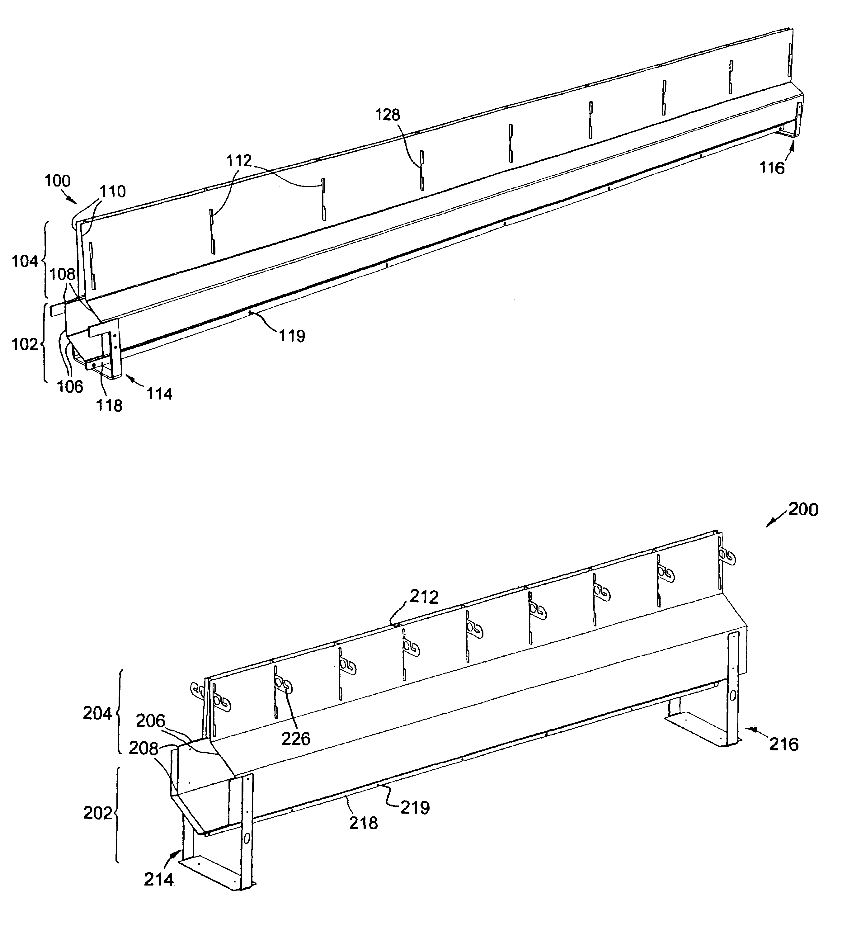
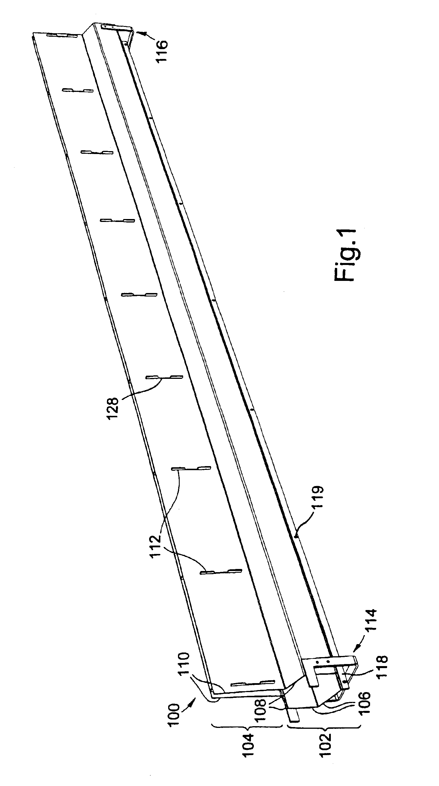
[0027]FIG. 1 shows a perspective view of a first slot drain according to the present invention, before bending the retaining projections into position;

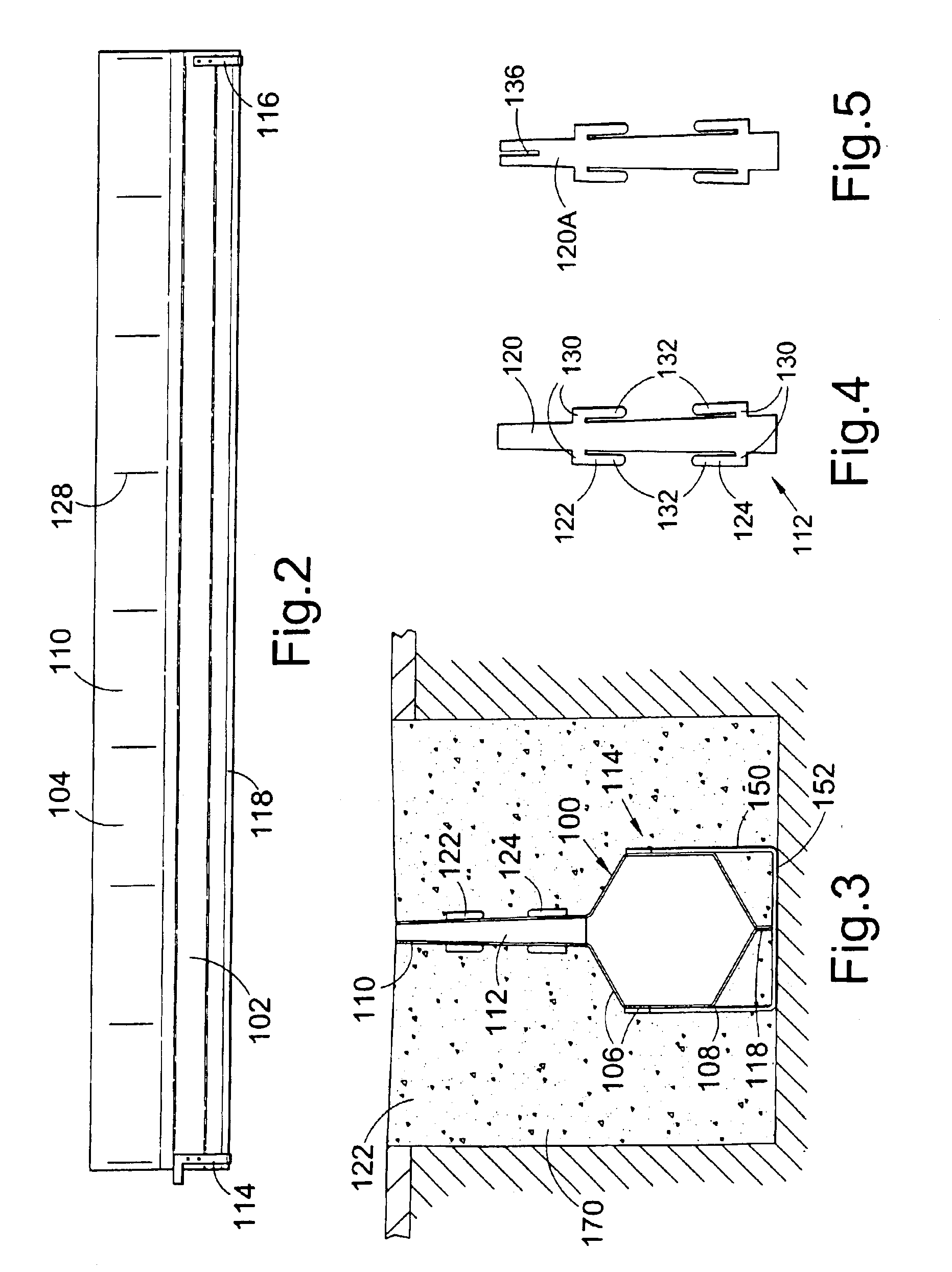
[0028]FIG. 2 shows a side view of the slot drain of FIG. 1;

[0029]FIG. 3 shows an end view of the slot drain of FIG. 1, installed in position;

[0030]FIG. 4 shows a separator in the slot drain of FIG. 1;

[0031]FIG. 5 shows an alternative separator according to the present invention;

[0032]FIG. 6 shows a side view of an end of the slot drain of FIG. 1, showing the end of another such slot drain, the retaining projection being shown bent into position;

[0033]FIG. 7 shows a perspective view of a second slot drain according to the present invention;

[0034]FIG. 8 shows a further perspective view of the slot drain of FIG. 7;

[0035]FIG. 9 shows a separator in the slot drain of FIG. 7;

[0036]FIG. 10 shows an end vie...


PUM


Abstract

A slot drain including a throat portion having two walls and a separator arranged to separate the two walls. The separator includes lateral projections passing through holes in the two walls. The lateral projections are bent over the two walls to retain the two walls against the separator as well as to maintain the separator in position.

Description

BACKGROUND OF THE INVENTION[0001]The present invention relates to drainage systems. More particularly, the present invention relates to slot drains or line drains, which facilitate high capacity drainage of surface water or other liquid through a narrow linear slot, while ensuring a high drainage capacity.[0002]Slot drains generally consist of cylindrical pipes or channels embedded beneath the surface to be drained with relatively narrow slots or throats extending upwardly from the pipe to the surface. Water present on the surface to be drained enters the throat through the opening in the surface and falls into the pipe or channel via which it is carried away to an appropriate drainage outlet, possibly via a silt box. The main advantage of slot drains is that, although the area of the drainage opening on the surface is small, the conduit along which the water is carried to the drainage outlet is large. This means that the drainage system can cope with heavy rainfall without requirin...

Claims


Application Information

Patent Timeline
Patent Type & Authority Patents(United States)
IPC IPC(8): E01C11/00E01C11/22E03F3/04E03F5/04
CPCE03F3/046E01C11/227E01C11/22
Inventor LITTLE, COLIN GEORGEBRADBEER, SIMON FRANCIS GODWIN
Owner ALUMASC
Why Eureka
Try Eureka