Flexible print circuit, wire harness, and wiring structure using shape memory material

a flexible print circuit and shape memory technology, applied in the direction of insulated conductors, cables, relatively moving parts, etc., can solve the problems of increasing labor and operating costs required for wiring operation, occupying space in electronic instruments, and unable to find suitable shape memory alloys, etc., to achieve easy deformation of shape memory materials, reduce operating costs, and facilitate shape restoration

Inactive Publication Date: 2005-06-14
FUJIFILM CORP +1
View PDF10 Cites 11 Cited by
  • Summary
  • Abstract
  • Description
  • Claims
  • Application Information

AI Technical Summary

Benefits of technology

[0009]The present invention has been designed in consideration of such circumstances, and it is an object thereof to provide a wiring structure according to which operating costs can be reduced and the reliability and stability of the wiring can be ensured when a wiring member such as a wire harness or FPC having a plurality of signal wires are connected.
[0031]According to the present invention as described above, operating costs can be reduced and the reliability and stability of the wiring can be easily ensured when a wire harness or flexible print circuit (FPC) having a plurality of signal wires are connected.

Problems solved by technology

Hence, it is sometimes impossible to find a suitable shape memory alloy for use as a wire rod which satisfies both of these conditions.
Moreover, in wire harnesses having a plurality of signal wires, the sectional area inevitably increases when the outer periphery is wrapped, thus taking up space within the electronic instrument.
Furthermore, with continuing reductions in the size and thickness of electronic instruments in recent years, it has become necessary to arrange wire harnesses or FPCs having a plurality of signal wires in extremely narrow gaps as if weaving between electronic components, and since the space for connecting the wire harnesses or FPCs with connectors inside the electronic instrument has also become extremely narrow, the labor and operating costs required for a wiring operation increase.

Method used


Image

  • Flexible print circuit, wire harness, and wiring structure using shape memory material
  • Flexible print circuit, wire harness, and wiring structure using shape memory material
  • Flexible print circuit, wire harness, and wiring structure using shape memory material

Examples


first embodiment

[0039][First Embodiment]

[0040]The main parts of a wiring structure of a first embodiment according to the present invention are illustrated in FIGS. 1A and 1B. FIG. 1A is a plan view of a flexible print circuit (to be referred to simply as “FPC” hereinafter) 100, and FIG. 1B is a sectional view along an A-B line thereof.

[0041]In FIGS. 1A and 1B, the FPC 100 is formed with an array of a plurality of signal wires 10 sandwiched on either side (in other words, at the two end portions 120 of the FPC 100 in the direction of width) by guiding core wires 20 constituted by a shape memory material. Note that although the signal wires 10 of the FPC 100 in FIG. 1B are arranged in coplanar form, the signal wires 10 may be arranged on a plurality of layers depending on the type of the FPC 100.

[0042]The signal wires 10 are conductors for transmitting predetermined electric signals in the direction of length. A connection portion 110 for connecting the signal wire 10 to a predetermined connector wi...

second embodiment

[0052][Second Embodiment]

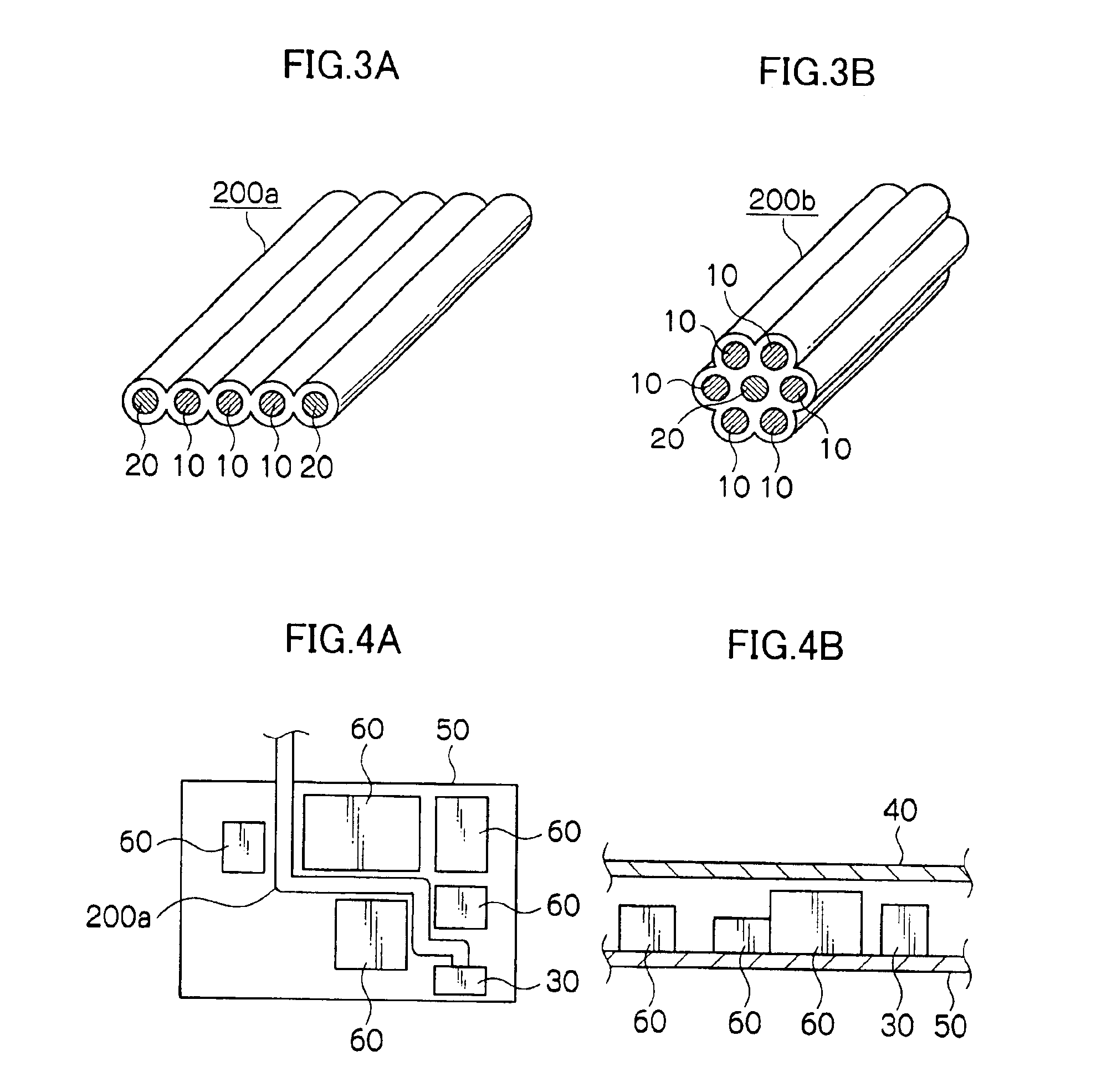
[0053]The main parts of a wiring structure of a second embodiment according to the present invention are illustrated in FIGS. 3A and 3B. FIG. 3A illustrates a wire harness 200a (a flat wire harness) in which a plurality of signal wires 10 are arranged in coplanar form and guiding core wires 20 for guiding the signal wires 10 are disposed on the two sides of the array of signal wires 10 in the direction of width (in other words, the two end portions of the wire harness 200a in the direction of width) FIG. 3B illustrates a wire harness 200b (a round wire harness) in which the plurality of signal wires 10 are disposed around the periphery of the guiding core wire 20.

[0054]The signal wires 10 are conductors for transmitting predetermined electric signals in the direction of length. An end portion of the signal wire 10 in the direction of length is connected to a predetermined connector within an electronic instrument. Note that in some cases, both ends are conne...

third embodiment

[0063][Third Embodiment]

[0064]In this embodiment, the round wire harness 200b shown in FIG. 3B is used, and a guiding core wire 20 of the wire harness 200b is caused to memorize a coiled shape in advance.

[0065]Here, the term “coiled shape” includes a spiral shape which is coiled upward, and a whorl shape which is wound in coplanar form. In the following description, an example in which the guiding core wire 20 memorizes a spiral shape as the wiring completion shape will be provided. Note that in this embodiment, the wire harness 200b shown in FIG. 3B is formed with narrow signal wires such that when the guiding core wire 20 is restored to the spiral shape, the entire wire harness 200b including the signal wires 10 deforms into the spiral shape together with the guiding core wire 20.

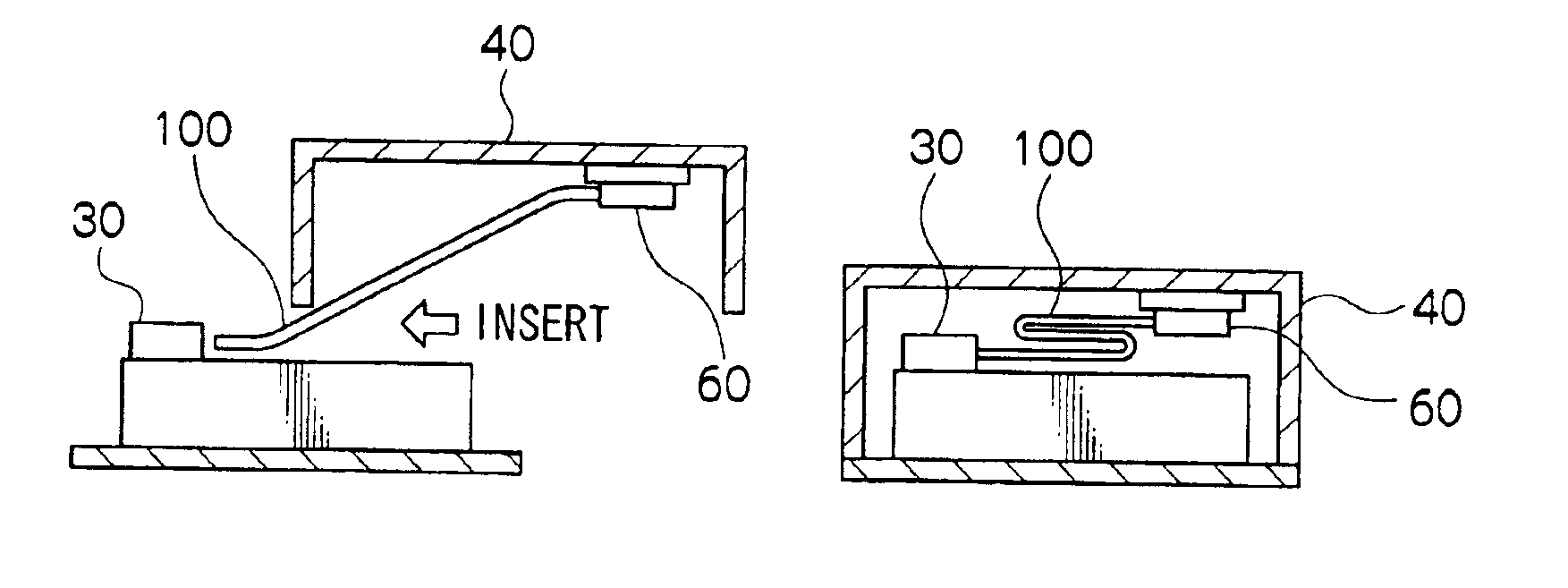
[0066]An example of a wiring operation of the wire harness 200b of this embodiment will be described using FIGS. 5A and 5B. FIG. 5A is a sectional view of an electronic instrument during insertion of the ...


PUM

PropertyMeasurementUnit
temperatureaaaaaaaaaa

Abstract

In a flexible print circuit having a plurality of signal wires, core wires formed from a shape memory material are provided on the two end portions thereof in the direction of width, and are caused to memorize a wiring completion shape within an electronic instrument in advance. In a wire harness having a plurality of signal wires, core wires formed from a shape memory alloy are disposed on the two sides of the planar signal wire array, or positioned along the central axis of the signal wires which are bundled into circular form. A guide frame for guiding a wire harness having a plurality of signal wires and which is caused to memorize in advance a shape which removes the wire harness from the movement range of a movable component within the electronic instrument.

Description

BACKGROUND OF THE INVENTION[0001]1. Field of the Invention[0002]The present invention relates to a wiring structure and, more particularly, to a wiring structure using a shape memory material.[0003]2. Description of the Related Art[0004]When a wiring member such as a wire harness or a flexible print circuit (FPC) is arranged in the gaps between electronic components or the like in an electronic instrument, the wiring member is typically formed so as to match the form of the gaps.[0005]It has been proposed in the prior art that a shape memory alloy be used to form a conductive wire rod (or a shape memory alloy pipe or the like for holding the wire rod) that is connected to a predetermined location. Here, the wire rod or the like is caused to memorize a wiring completion shape in advance, and is then deformed into an arbitrary shape and connected to a wire rod terminal. The wire rod is then heated so as to recover the wiring completion shape (see Japanese Patent Application Publicatio...

Claims


Application Information

Patent Timeline
Patent Type & Authority Patents(United States)
IPC IPC(8): H01R4/01H05K1/00H05K7/00H01B7/00H01B7/08H02G11/00H05K7/14
CPCH01R4/01H05K1/028H01R12/59H05K2201/10287H05K2201/2009H05K2201/0308
Inventor FUJIMURA, YUICHI
Owner FUJIFILM CORP
Why Eureka
Try Eureka