

Current mode bang-bang controller in a switching voltage regulator
- Summary
- Abstract
- Description
- Claims
- Application Information
AI Technical Summary
Problems solved by technology
Method used
Image

Examples
first embodiment
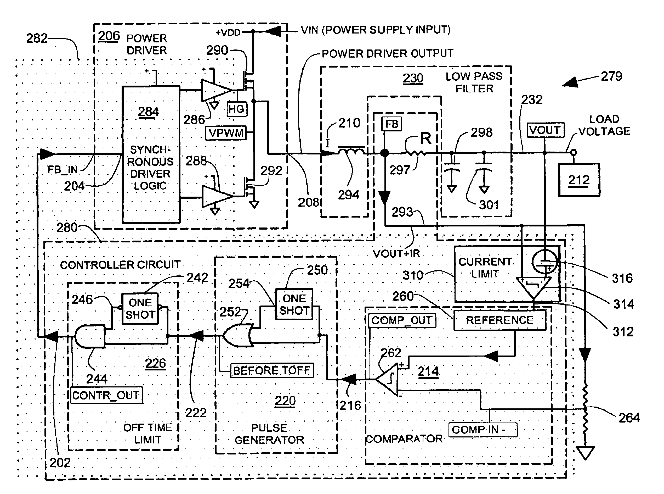
[0029]FIG. 3 illustrates a regulator 201 that includes a controller circuit 200. The controller circuit 200 couples a controller output 202 to a feedback input 204 of a power driver 206. The power driver 206 provides a power driver output 208. The power driver output 208 couples a power driver current I (at 210) to a load 212, and maintains a load voltage VOUT at 232. The power driver 206 serves to energize the electrical load 212 with a relatively constant voltage. The power driver current I passes through an impedance Z (at 295) that is connected to load voltage output VOUT at 232. The arrangement of the impedance Z connected to VOUT generates a voltage on line 293 that is a combination of the load voltage VOUT and the power driver current I that is approximately VOUT+ZI. The impedance Z serves as a weighting factor so that the voltage on line 293 is a weighted sum of the load voltage and the power driver current.
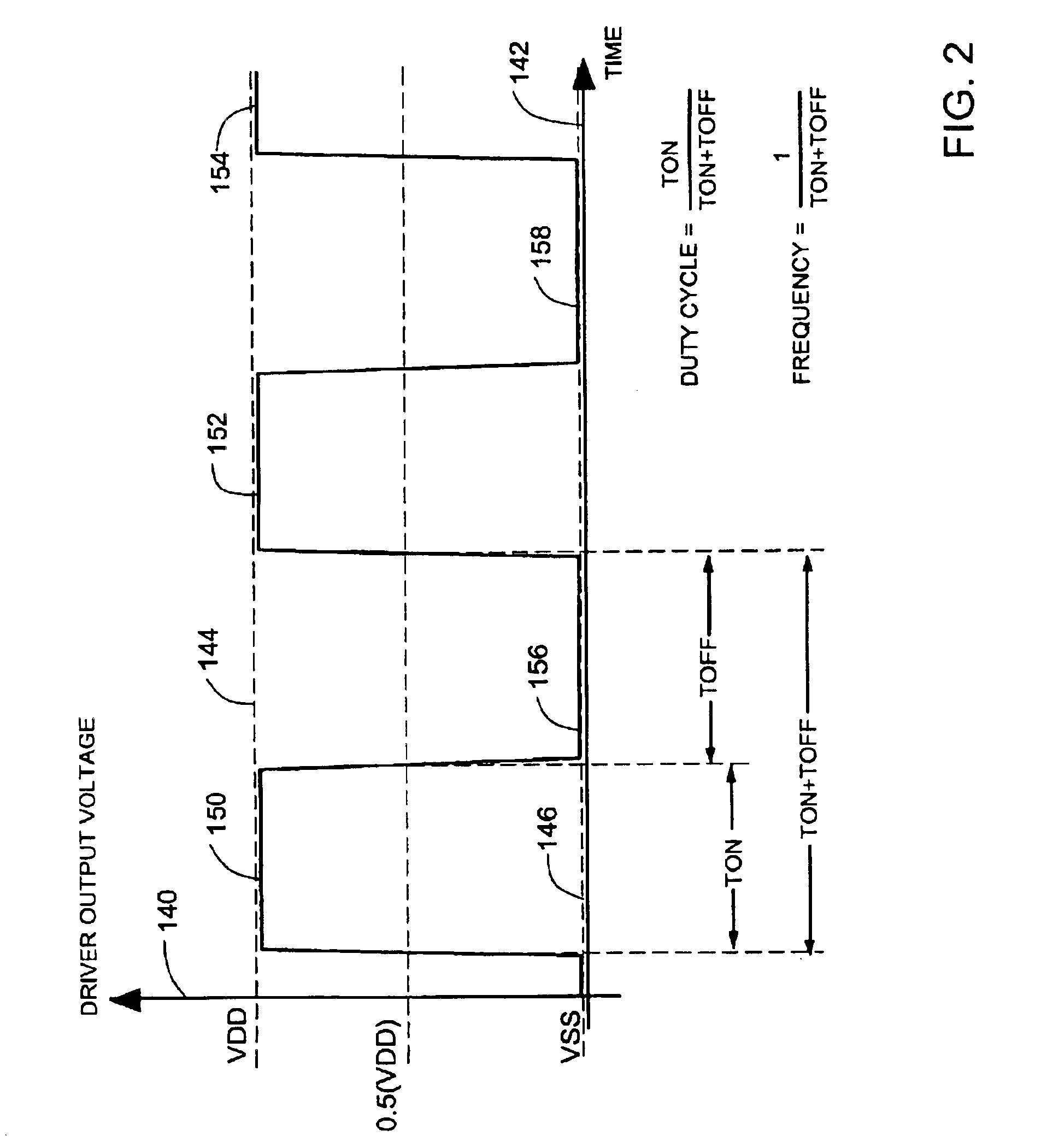
[0030]The controller output 202 has a duty cycle that varies as a fu...
second embodiment
[0035]FIG. 4 illustrates a regulator 239 that includes a controller circuit 240. Reference numbers used in FIG. 4 that are the same as reference numbers used in FIG. 3 identify the same or similar features. An off time limit circuit 226 comprises a first one shot circuit 242 and an AND gate 244. A first input of the AND gate 244 is coupled to an output 246 of the first one shot circuit 242. The pulse output 222 couples to a second input of the AND gate 244 and to an input of the first one shot circuit 242. The first one shot 242 has a one shot pulse width that sets an off time limit. When the one shot 242 is triggered by a falling edge of the pulse output 222, the one shot output 246 goes to a low level and provides blanking so that subsequent pulses from the pulse output 222 that are too closely spaced are blanked at the AND gate 244 and do not pass through to the output of the AND gate 244.
[0036]The pulse generator 220 comprises a second one shot circuit 250 and an OR gate 252. On...
third embodiment
[0039]FIG. 5 illustrates a regulator 279 that includes a controller circuit 280 with variable OFF time and an OFF time limit. Reference numbers used in FIG. 5 that are the same as reference numbers used in FIG. 4 identify the same or similar features.
[0040]The controller circuit 280 is preferably formed as an integrated circuit 282 indicated by a dotted line surrounding portions of circuitry that are included in the integrated circuit. Other functional blocks (not illustrated) can also be included in the integrated circuit 282. In addition to the controller circuit 280, the integrated circuit 282 can also include synchronous driver logic 284 and drivers 286, 288 that are part of the power driver 206. The components of integrated circuit 282 are preferably all produced on a single silicon chip for low cost production. The integrated circuit 282 can be a predominantly digital integrated circuit, limiting the use of complex linear amplifier circuitry that uses large areas of silicon re...
PUM
 Abstract
Description
Claims
Application Information