Fast-locking bang-bang pll with low ouput jitter

a phase detector and fast lock technology, applied in the field of phaselocked loops, can solve the problems of low output jitter, analog pd has the disadvantage of only giving information on the mathematical sign or polarity of the phase error rather than on the signed magnitude, and achieves the effect of improving jitter (phase noise) performance in lock, fast lock times, and low cos

Active Publication Date: 2011-04-14
NXP BV
View PDF8 Cites 3 Cited by
  • Summary
  • Abstract
  • Description
  • Claims
  • Application Information

AI Technical Summary

Benefits of technology

[0009]It is therefore an object of the present invention to provide a simple and fast-locking bang-bang PLL with low output jitter, namely to provide a simple digital PLL able to achieve fast lock times while improving jitter (phase noise) performance in lock.

Problems solved by technology

However, the BBPD has the disadvantage, in comparison to an analog PD, to give information only on the mathematical sign or polarity of the phase error rather than on the signed magnitude.
Thus, the BBPD suffers from a jitter versus frequency tracking range trade-off, such that a trade-off must be found between output jitter in the time domain (or phase noise in the frequency domain), and DPLL lock time.
Indeed, a small response to the BBPD output leads to low output jitter, but also causes long DPLL lock times. Reversely, fast locking by strongly responding to the BBPD output causes high jitter when in phase lock.
But apart from being slightly off in frequency, there is still no guarantee for phase lock at all, since the phase may be off by as much as 180 degrees.
Achieving phase lock may still take much time, especially when the reaction of the DPLL 100 to a measured phase error is small in order to obey the jitter (phase noise) specification for example.
However, the major drawback of the TDC is its inherent design, which is far more complex than the BBPD design.

Method used


Image

  • Fast-locking bang-bang pll with low ouput jitter
  • Fast-locking bang-bang pll with low ouput jitter
  • Fast-locking bang-bang pll with low ouput jitter

Examples


Embodiment Construction

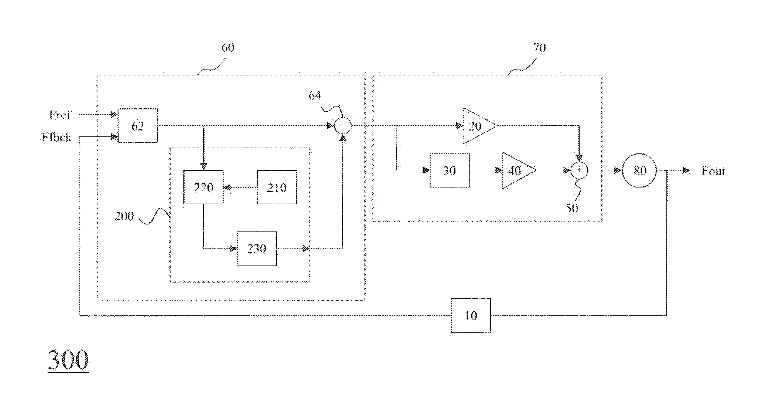
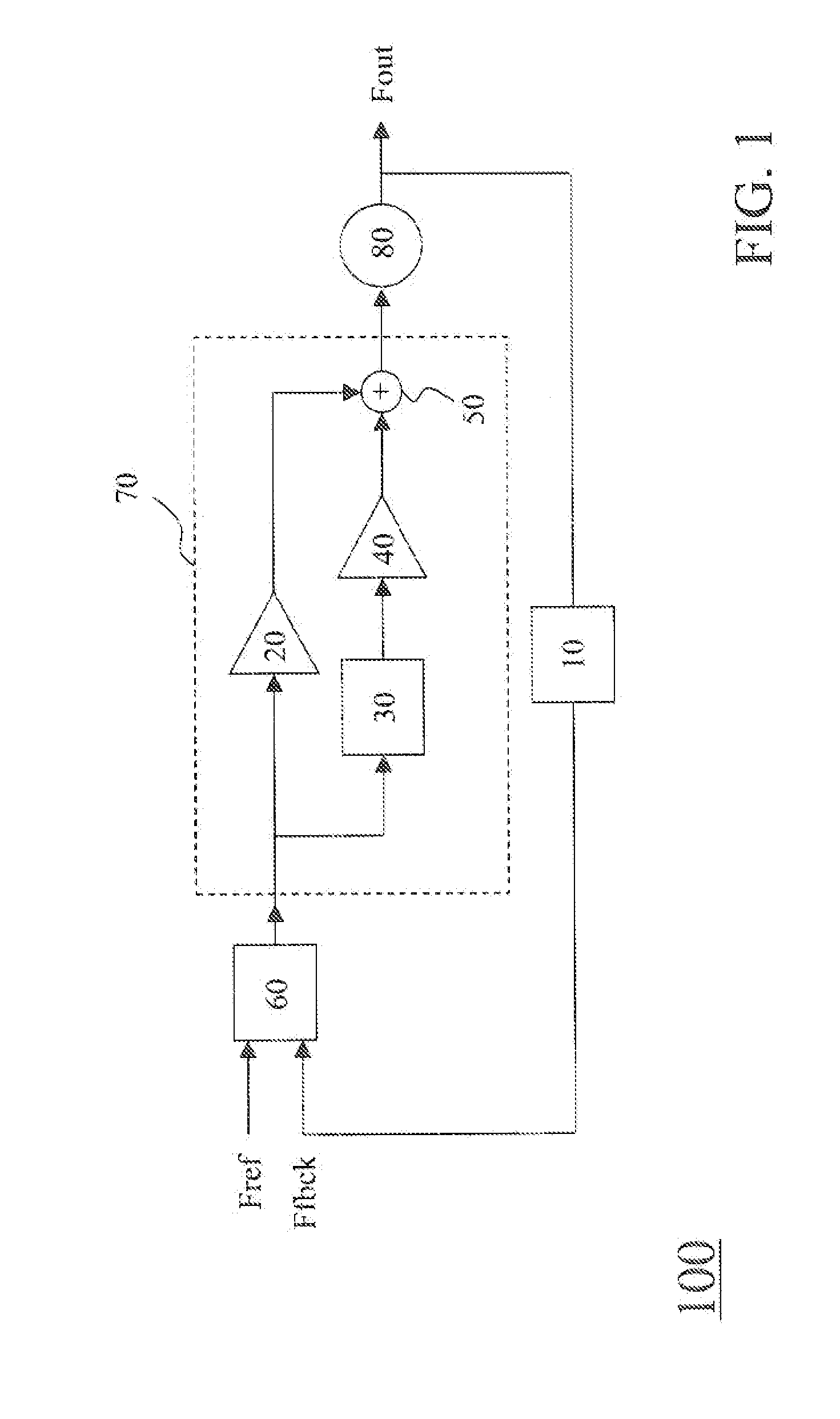
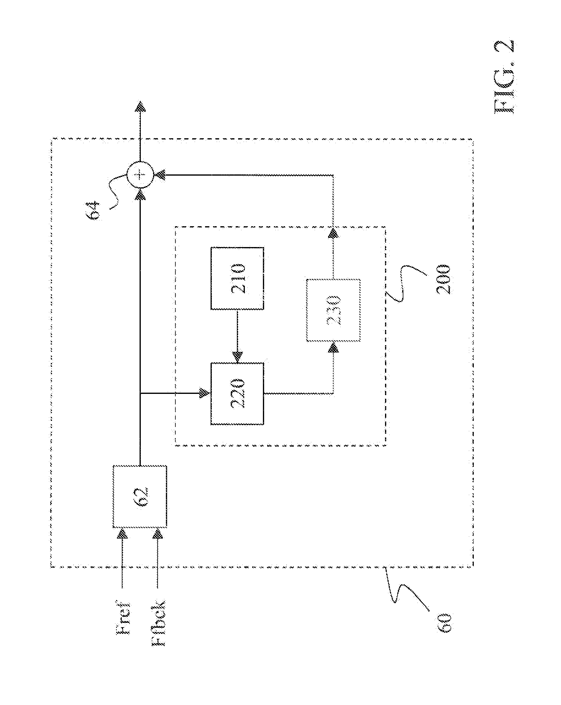
[0050]FIG. 2 shows a P2D 60 having an enhanced BBPD according to an embodiment of the present invention. Such a P2D 60 comprises a stand-alone BBPD 62, an additional digital circuit 200 including a sign detector 210, a counter 220 and a mapping function 230, and a summer block 64.

[0051]In order to have a configuration as simple as possible, the BBPD 62, which is also a single-bit phase digitizer or single-bit phase detector, may be implemented by a single flip-flop for example. During the phase-locking process, it detects a phase difference at its input and outputs a digital value indicating the amount of phase error ε it sees at its input. The digital value is in the form of data bits of value either “+1” or “−1” depending on the sign “+” or “−” of the detected phase difference, which sign change may occur at the zero-crossing at phase zero-degree or 180-degrees. This polarity sign “+” or “−” is detected by the sign detector 210, which provides the counter 220 with a reset signal w...


PUM


Abstract

The present invention relates to a gigitaol phaselocked loop DPLL (300, 400) having a phase-to-digital P2D (60) with an enhanced bang-bang phase detector BBPD. Such a P2D (60) comprises a BBPD (62), an additional digital circuit (200) including a sign detector (210), a counter (220) and a mapping function (230), and a summer block (64). During the locking process, the BBPD (62) may-output a repeating value, namely a string of data bits of same polarity value either “+1” or “−1”. The polarity sign is detected by the sign detector (210), and the data string length is determined by the counter (220) that is reset to zero whenever the BBPD output changes sign. The mapping function (230) is configured for mapping the data string length in input to the phase correction level in output Its output is added to that of the BBPD (62) through the summer block (64), such that the phase correction level is increased to enhance the locking process whenever a data string is detected.

Description

FIELD OF THE INVENTION[0001]The present invention relates to the field of phase-locked loops, and more particularly to digital phase-locked loops with a bang-bang phase detector.BACKGROUND OF THE INVENTION[0002]Since the first phase-locked loop (PLL) designed in the 1930s for use in radio receivers, the phase locking concept has been applied to many applications ranging from generating clock signals in microprocessors to synthesizing frequencies. A conventional analog PLL is basically an oscillator whose frequency is locked onto some frequency component of an input signal. In the forward path, a phase detector (PD) compares the phase of the input signal to the phase of an output signal, and generates an output that is proportional to the phase difference. The output of the PD is filtered by an analog loop filter and then used to control the frequency of a voltage-controlled oscillator (VCO). An optional divider can be used in the feedback path for frequency multiplication. Through t...

Claims


Application Information

Patent Timeline
Patent Type & Authority Applications(United States)
IPC IPC(8): H03L7/08
CPCH03L7/091H03L7/085
Inventor VAN DE BEEK, REMCO CORNELIS HERMAN
Owner NXP BV
Why Eureka
Try Eureka