
Magnetostrictive position measuring method and system for changing a duration of a next excitation pulse as a function of the ascertained position of the magnet and the associated excitation pulse corrective value

a technology of magnetic field and excitation pulse, which is applied in the direction of measurement devices, magnitude/direction of magnetic fields, sensor output conversion, etc., can solve the problem of affecting the minimum period of time in which interrogation pulses can be processed, and achieve the effect of shortening the time interval

Inactive Publication Date: 2005-06-14
HORST SIEDLE GMBH & CO KG
View PDF3 Cites 5 Cited by
  • Summary
  • Abstract
  • Description
  • Claims
  • Application Information

AI Technical Summary

Benefits of technology

[0008]An object of the present invention is to create a magnetostrictive position measuring method and a corresponding position measuring system which allows shorter time intervals between the individual interrogation pulses.
[0012]From this, there results the advantage that the position of the object ascertained by the position calculation unit can be used further immediately. The time necessary for a correction is therewith saved. This at the same time represents a shortening of that minimal period of time which is required for ascertaining a position of the object.
[0014]This has as a consequence that the minimum period of time in which interrogation pulses can be processed no longer depends on the time required for correction of the ascertained position. This leads to the possibility that with the position measuring system of the invention, shorter time intervals between the individual interrogator impulses can be allowed.
[0017]Furthermore, according to an embodiment of the present invention, the position calculation unit is provided to conduct the ascertainment of the position on the basis of the duration using a standardized rate of propagation of the torsion wave on the waveguide. This is possible without further ado since (as was explained), the correction has already been conducted in the framework of generating the excitation pulse. The conversion of the duration into the position of the object can therewith be conducted extremely simply and rapidly.

Problems solved by technology

The disadvantage of the described magnetostrictive position measuring method or system includes among other things in that the minimum period of time in which interrogation pulses can be processed depends upon the time necessary for correction of the ascertained position.

Method used


Image

  • Magnetostrictive position measuring method and system for changing a duration of a next excitation pulse as a function of the ascertained position of the magnet and the associated excitation pulse corrective value
  • Magnetostrictive position measuring method and system for changing a duration of a next excitation pulse as a function of the ascertained position of the magnet and the associated excitation pulse corrective value
  • Magnetostrictive position measuring method and system for changing a duration of a next excitation pulse as a function of the ascertained position of the magnet and the associated excitation pulse corrective value

Examples


Embodiment Construction

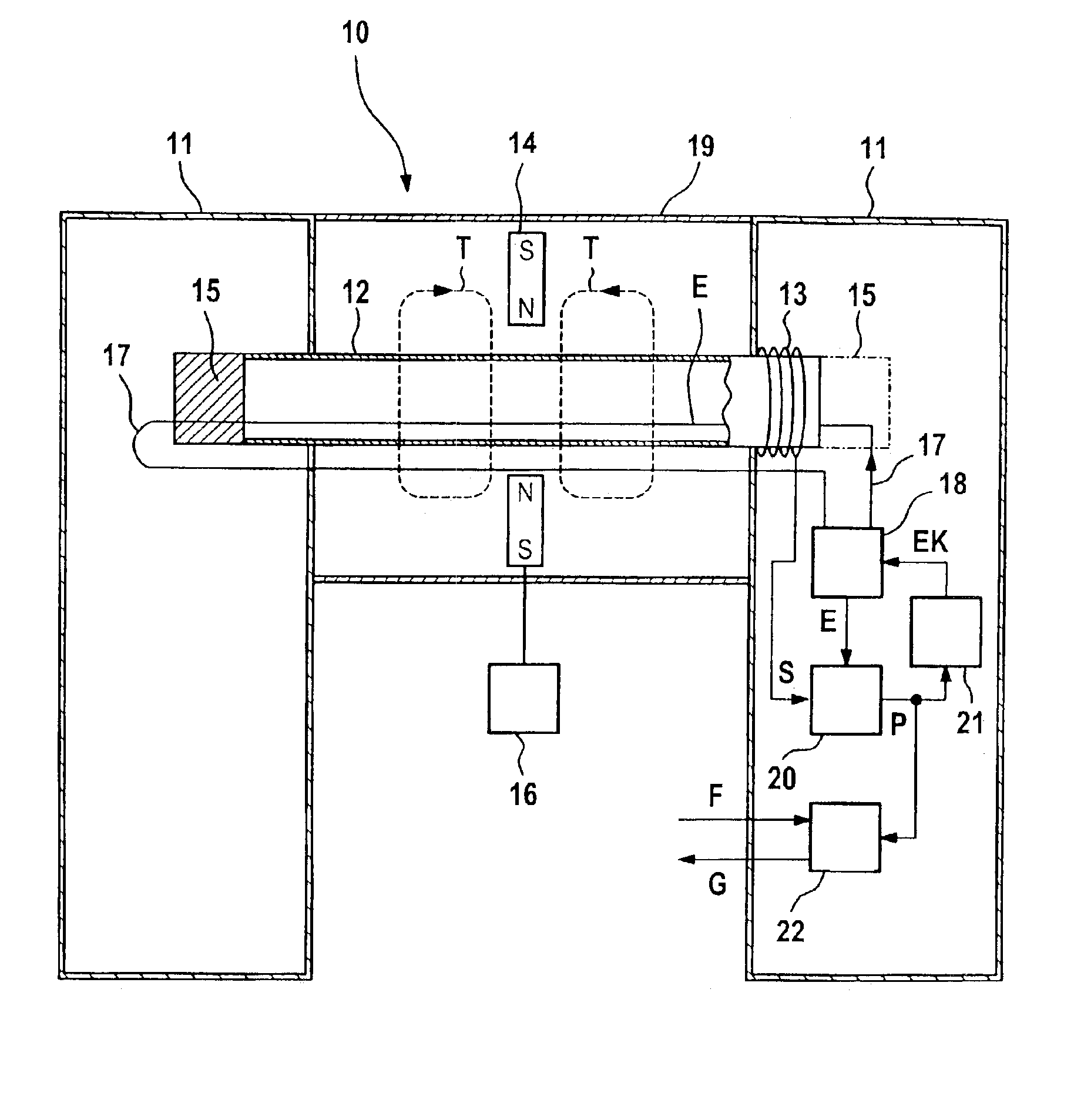
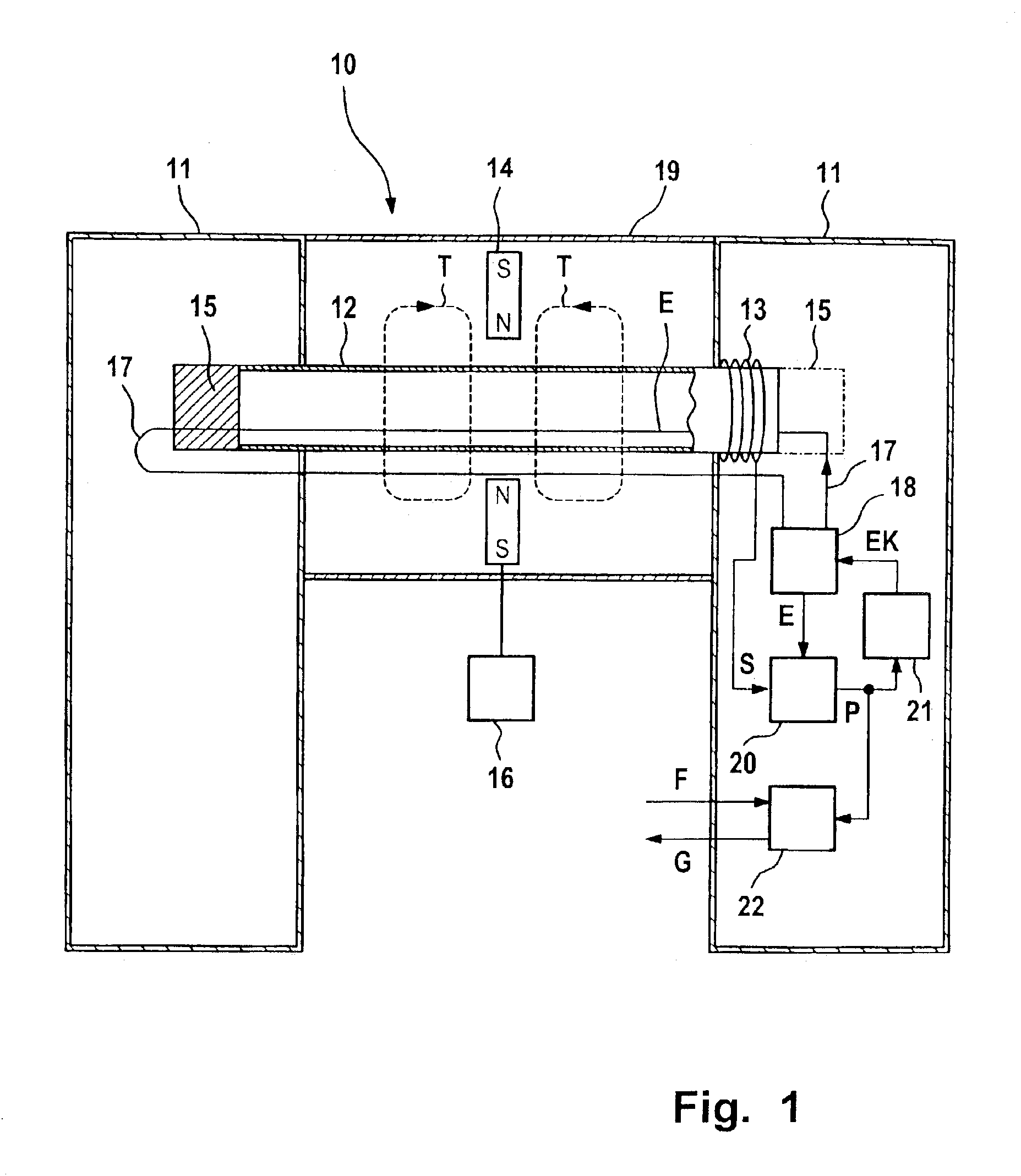
[0023]FIG. 1 illustrates a magnetostrictive position measuring system 10 which has a housing 11, a waveguide 12, a reel 13 and a magnet 14.

[0024]The waveguide 12 consists of magnetostrictive material and is constructed rod-like. The reel 13 is arranged in the region of the one end of the waveguide 12. The reel 13 encircles the waveguide 12 without touching the latter. A damper 15 is provided in the region of the other end of the waveguide 12. In addition, a further damper 15 can be present in that region of the waveguide 12 in which the reel 13 is arranged.

[0025]The magnet 14 can be slid in the direction of the waveguide 12. The magnet 14 is connected with an object 16 so that the position of the magnet 14 along the waveguide 12 corresponds to the position of the object 16.

[0026]A conductive wire 17 is connected with a pulse generator 18. The wire 17 extends through the interior of the entire length of the waveguide 12 and is conducted back on the exterior of the waveguide 12 to the...


PUM


Abstract

A magnetostrictive position measuring system is provided with a waveguide and which is allocated with a magnet movable along the waveguide. An impulse generator for generating an excitation pulse and a conductive wire for guiding the excitation pulse through the waveguide to the magnet are provided, whereby a torsion wave arises in the waveguide when the excitation pulse reaches the magnet. A reel for generating a reply pulse as a function of the torsion wave and a position calculation unit for ascertaining the position of the magnet as a function of the excitation pulse and the reply pulse are provided. A processor is provided in which a table is present in which a large number of positions and excitation pulse correction values are allocated to one another. The duration of the next excitation pulse is altered as a function of the position of the magnet ascertained and the associated excitation pulse correction value from the table.

Description

[0001]The present application hereby claims priority under 35 U.S.C. §119 on German patent application number 101 64 121.4 filed Dec. 24, 2001, the entire contents of which are hereby incorporated herein by reference.FIELD OF THE INVENTION[0002]The present invention generally relates to a magnetostrictive position measuring method for determining the position of a magnet where the magnet is movable along a wave guide in which an excitation pulse is generated and is passed through the wave guide to the magnet, in which a torsion wave arises in the wave guide when the excitation pulse reaches the magnet, in which a reply pulse is generated as a function of the torsion wave, and in which the position of the magnet is ascertained as a function of the excitation pulse and the reply pulse. The present invention also generally relates to a corresponding magnetostrictive position measuring system.BACKGROUND OF THE INVENTION[0003]A position measuring method or position measuring system is kn...

Claims


Application Information

Patent Timeline
Patent Type & Authority Patents(United States)
IPC IPC(8): G01D5/48
CPCG01D5/485
Inventor EHLING, ERNST
Owner HORST SIEDLE GMBH & CO KG
Learn More