Variable-gain differential input and output amplifier

Inactive Publication Date: 2005-06-14
ST ERICSSON SA
View PDF8 Cites 10 Cited by
  • Summary
  • Abstract
  • Description
  • Claims
  • Application Information

AI Technical Summary

Benefits of technology

[0011]The disclosed embodiments of the present invention provide a variable-gain amplifier with a differential input and output, the gai

Problems solved by technology

If not, the amplifier half which receives voltage V1in and generates voltage V1out and the amplifier half which receives voltage V2in and generates voltage V2out have different gains and bandwidths, which

Method used


Image

  • Variable-gain differential input and output amplifier
  • Variable-gain differential input and output amplifier
  • Variable-gain differential input and output amplifier

Examples


Embodiment Construction

[0021]Only those elements necessary to the understanding of the present invention have been shown in the following drawings. Same reference numbers represent the same elements in the previous drawing and in the following drawings.

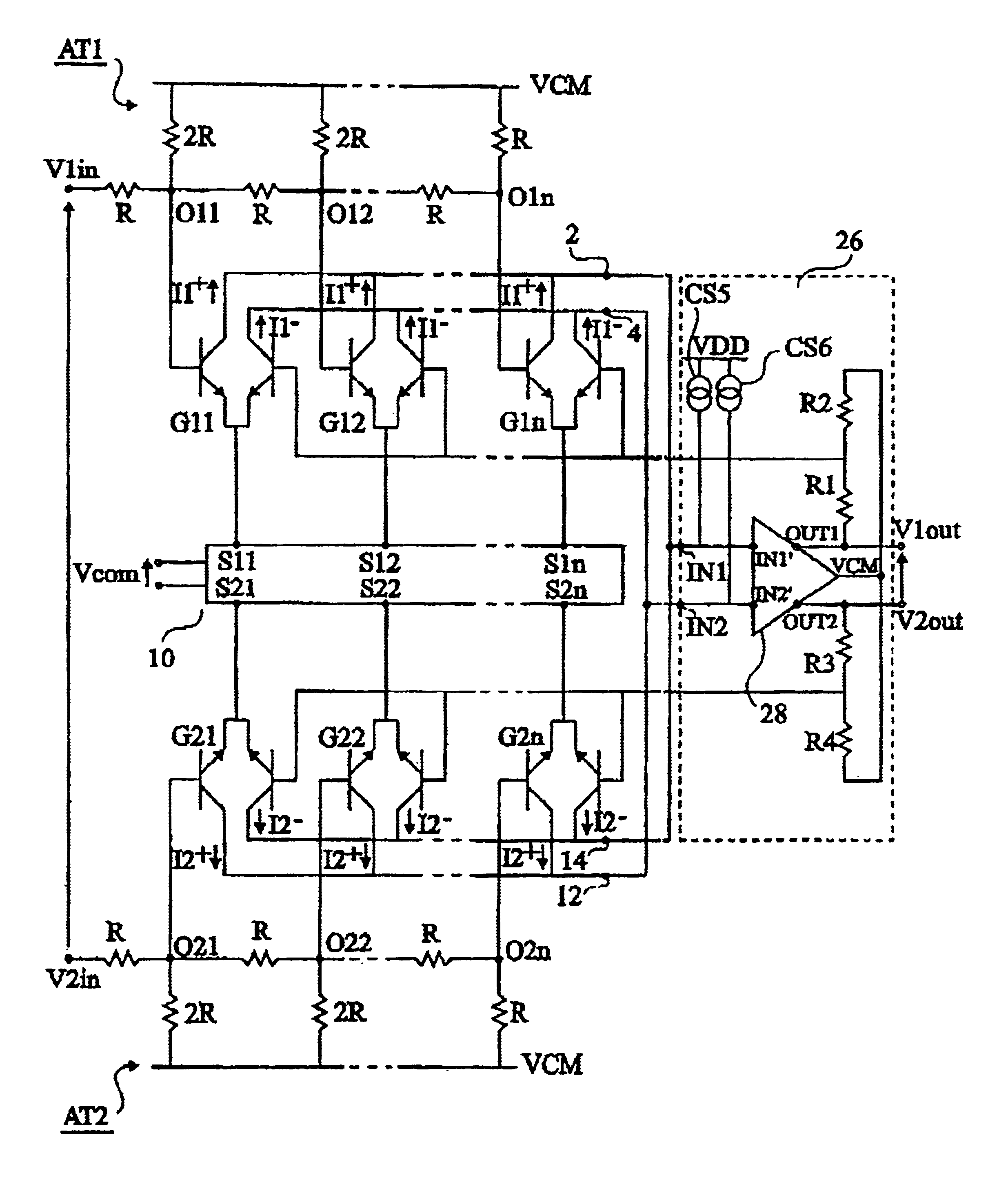
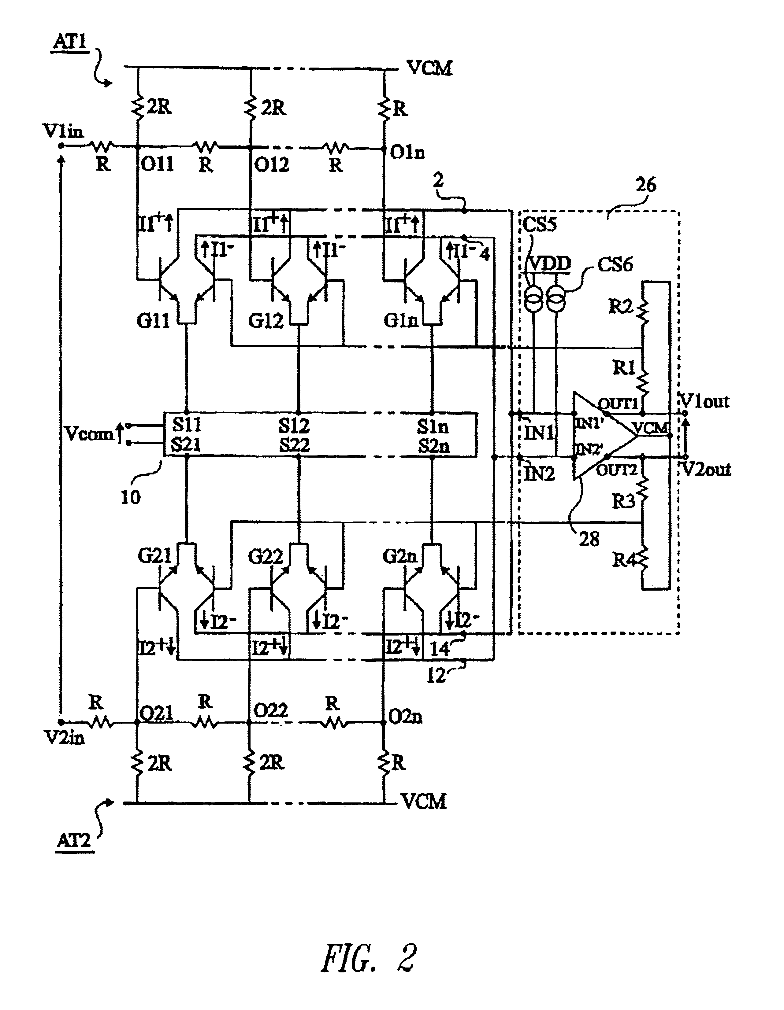
[0022]FIG. 2 schematically shows an embodiment of a variable-gain amplifier according to the present invention, intended for receiving a differential voltage V1in-V2in and for providing as a response a differential voltage V1out-V2out. The amplifier includes a first attenuator network AT1 of R / 2R type receiving voltage V1in on an input terminal and having n output nodes O1i. According to the present invention, attenuator network AT1 is referenced to common mode voltage VCM of the amplifier output. The amplifier includes a first assembly of transconductor elements G1i controllable by a current, each of which receives on a first input the voltage generated by the node O1i of same rank i. Each transconductor element G1i includes a pair of bipolar transistors, ...


PUM


Abstract

A variable-gain amplifier with a differential input and differential output, including an attenuator block, receiving an input voltage and providing, on several outputs, voltages, each of which is equal to the attenuated input voltage; differential transconductor elements, each having a first input connected to a respective output of the attenuator block, and generating first and second positive currents and first and second negative currents; a current source assembly adapted to controlling the transconductance of each differential transconductor element according to an analog control signal; and an output block converting first and second input currents into a differential output voltage and providing a second input of each differential transconductor element with a feedback voltage depending on the output voltage.

Description

BACKGROUND OF THE INVENTION[0001]1. Field of the Invention[0002]The present invention relates to a variable-gain amplifier, and in particular to such an amplifier with differential input and output, the gain of which varies exponentially as a response to an analog control voltage, and having a small harmonic distortion and reduced noise.[0003]2. Description of the Related Art[0004]FIG. 1 schematically shows an amplifier, which can be made in integrated circuit form, having a gain that varies exponentially as a response to an analog control voltage Vcom. The amplifier is intended for receiving a differential voltage V1in-V2in and for providing as a response a differential voltage V1out-V2out.[0005]Voltage V1in is provided to an attenuator network AT1 referenced to a ground potential GND and having n output nodes O1i (i ranging between 1 and n). Each output node O1i generates a control voltage equal to input voltage V1in attenuated according to a predetermined ratio, for example 2i wh...

Claims


Application Information

Patent Timeline
IPC IPC(8): H03G7/00H03G7/08
CPCH03G7/08
Inventor MOURET, MICHELSABUT, MARCVAN ZANTEN, FRAN.CEDILLA.OIS
Owner ST ERICSSON SA
Why Eureka
Try Eureka