Wavelength discriminated image dithering

a wavelength discrimination and image technology, applied in the field of display images, can solve problems such as limited display resolution

Active Publication Date: 2005-06-14
TEXAS INSTR INC
View PDF21 Cites 27 Cited by
  • Summary
  • Abstract
  • Description
  • Claims
  • Application Information

AI Technical Summary

Problems solved by technology

Thus the resolution of the display is limited by the number of micromirrors that ca...

Method used


Image

  • Wavelength discriminated image dithering
  • Wavelength discriminated image dithering
  • Wavelength discriminated image dithering

Examples


Embodiment Construction

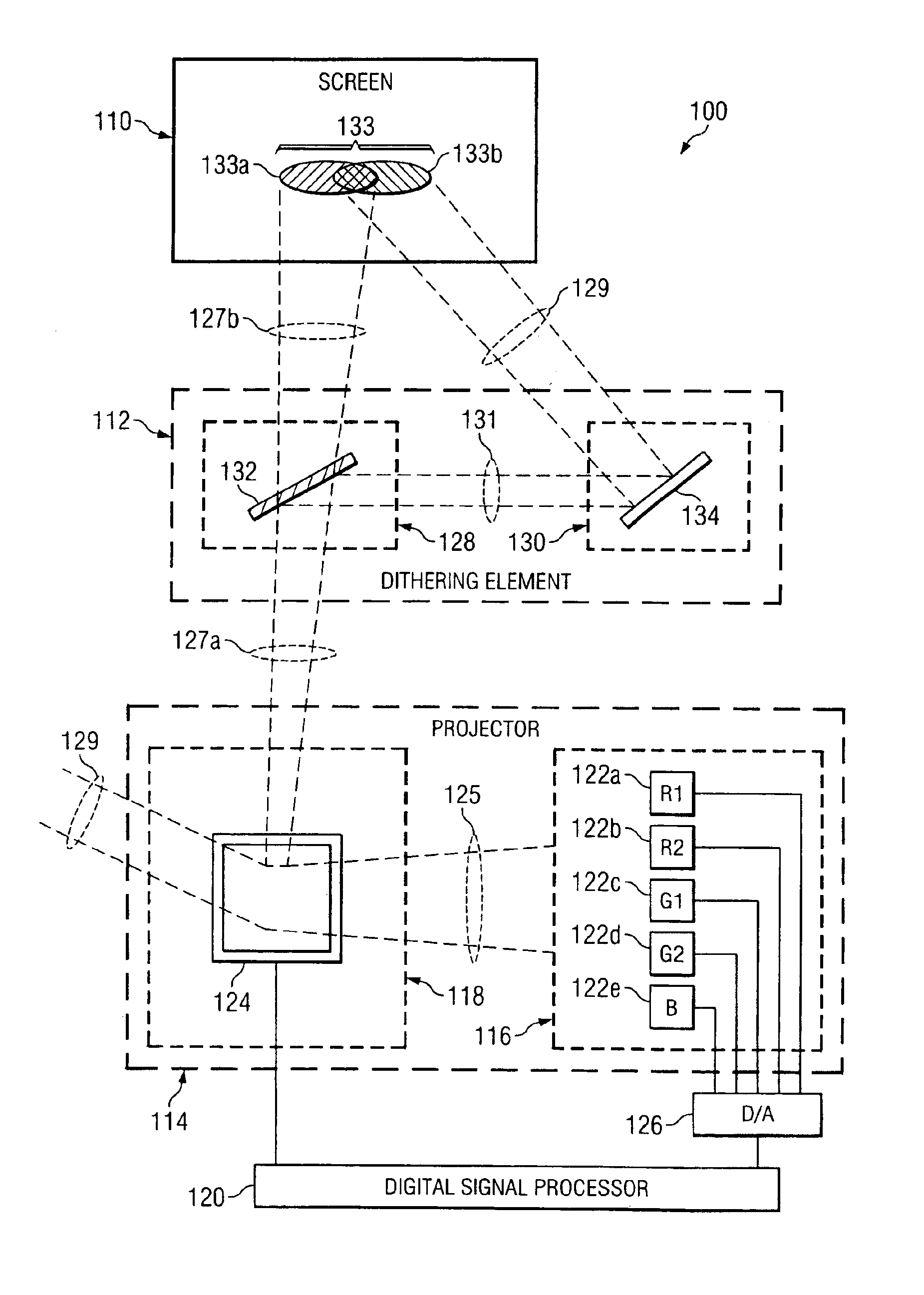
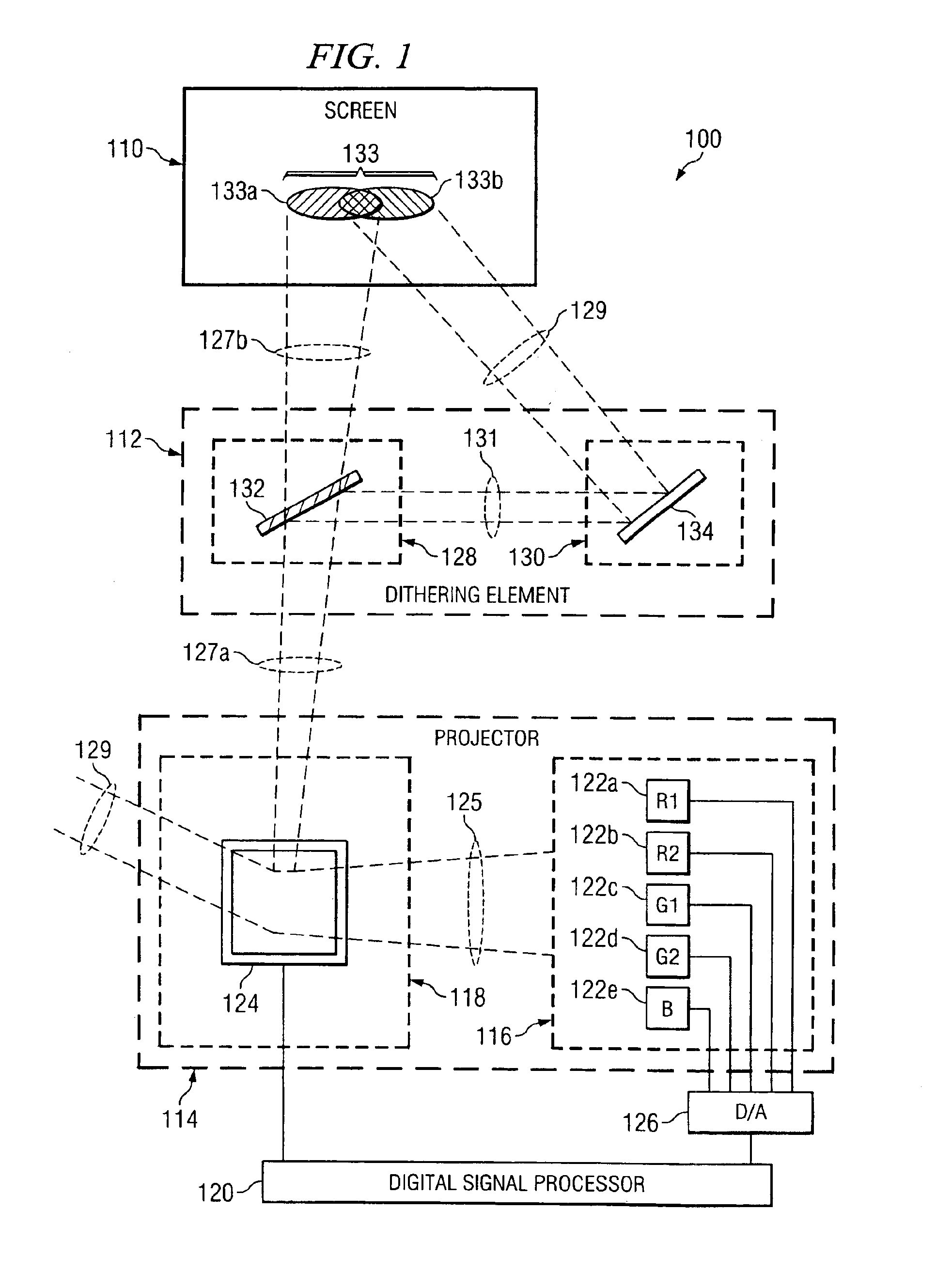
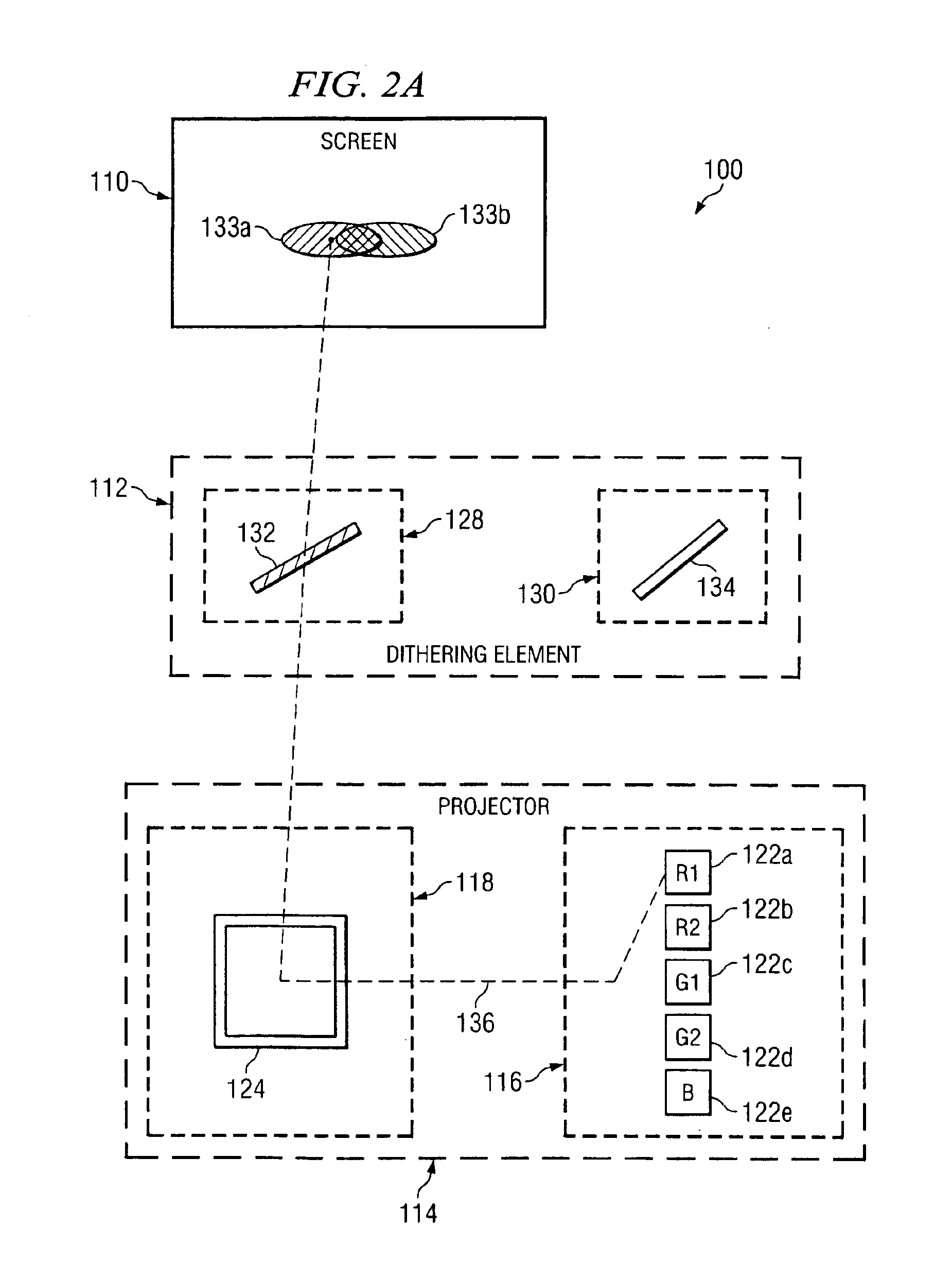
[0014]FIG. 1 illustrates one embodiment of a projection display system 100 that uses a dithering element 112 to provide a dithered image. Projection display system 100 includes a digital signal processor 120, a projector 114, a dithering element 112, and a screen 110. In general, digital signal processor 120 provides image information associated with a color image to projector 114. Dithering element 112 receives color-specific images from projector 114 and provides a projection image 133A and an offset image 133B for display on screen 110. Other embodiments of projection display system 100 may be employed without departing from the scope of this disclosure.

[0015]Projector 114 is optically coupled to dithering element 112 and is operable to provide color-specific image to dithering element 112. A “color-specific image”, as used herein, means a monochromatic portion of a color image. Projector 114 is electrically coupled to digital signal processor 120 and is operable to receive infor...


PUM


Abstract

A method and system for providing a dithered image is provided. In one embodiment, a projector system for providing a dithered image includes a light source comprising a first and a second light emitting diode (LED). The first LED is operable to transmit a first light beam at a first peak wavelength. The second LED is operable to transmit a second light beam at a second peak wavelength. The first peak wavelength is disparate from the second peak wavelength. A digital micromirror device (DMD) is operable to receive the first beam and the second beam and selectively pass a first portion of the first beam and a second portion of the second beam along a projection path. A dichroic reflector operable to receive the first portion and the second portion, passively pass the first portion along the projection path, and substantially reflect the second portion within a wavelength range. An optical mirror operable to receive the substantially reflected second portion and reflect the substantially reflected second portion along an offset path.

Description

TECHNICAL FIELD[0001]This invention relates generally to displaying images, and more particularly to wavelength discriminated image dithering.BACKGROUND[0002]Light processing systems often involve combining various primary colors of light on a display such that a particular color and / or image is produced. One way of effecting such combination is through the use of digital micromirror devices (DMD) available from Texas Instruments. In general, primary colors of light are shined on a DMD array having numerous micromirrors. Each micromirror is selectively controlled to reflect each primary color of light onto a particular portion of a display, such as a pixel. Each micromirror can be used to switch a pixel on or off by changing an angle of a corresponding mirror. The pixels of the DMD can maintain their “on” or “off” state for controlled display times. Conventionally, either three or more separate color-specific light sources are used or a single white-light source is used in combinati...

Claims


Application Information

Patent Timeline
IPC IPC(8): G02F1/00G02F1/29G09G3/00G02B27/14H04N9/31
CPCG02B27/1033G02B27/143H04N9/3197H04N9/3164H04N9/3188H04N9/3111
Inventor RUSSELL, ANDREW IAN
Owner TEXAS INSTR INC
Why Eureka
Try Eureka