Sheet processing apparatus, control method therefor, sheet processing method, and storage media

Inactive Publication Date: 2005-06-21
CANON KK
View PDF5 Cites 41 Cited by
  • Summary
  • Abstract
  • Description
  • Claims
  • Application Information

AI Technical Summary

Benefits of technology

[0036]To attain the above objects, according to a fifth aspect of the present invention, there is provided a method of controlling a sheet processing apparatus having sheet processing means for executing a sheet process to a sheet, conveying means for conveying the sheet to be processed by the sheet processing means, and detecting means for detecting an end position of the sheet in a direction at a right angle relative to a conveying direction of the sheet, the method comprising a c

Problems solved by technology

This method, however, has disadvantages: For example, the bundle of sheets may be too thick to be punched depending on the number of sheets in the bundle to be processed, and taking such a problem into consideration, a large-scale punching unit must be provided.
Further, during the punching process, it is impossible to convey a new sheet, or depending on the capacity of the punching unit, the punching process has to be carried out in a

Method used


Image

  • Sheet processing apparatus, control method therefor, sheet processing method, and storage media
  • Sheet processing apparatus, control method therefor, sheet processing method, and storage media
  • Sheet processing apparatus, control method therefor, sheet processing method, and storage media

Examples


first embodiment

[First Embodiment]

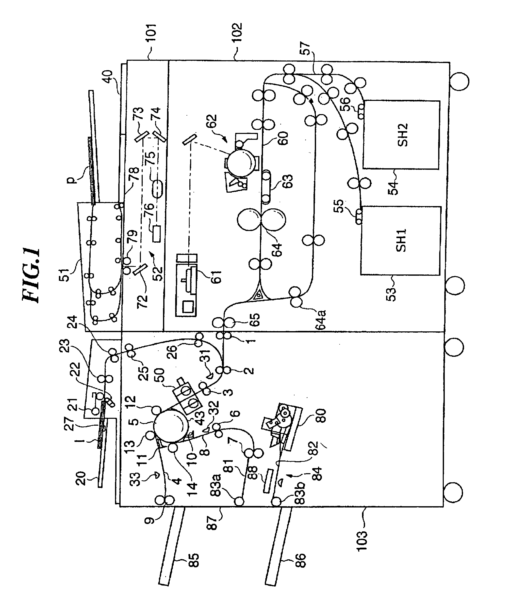
[0055]FIG. 1 is a sectional view showing the entire construction of an image forming system to which a sheet processing apparatus according to a first embodiment of the present invention is applied. The image forming system is comprised of a reading and sheet feeding apparatus 101, an image forming apparatus 102, a sheet processing apparatus 103, and others.

[0056]The reading and sheet feeding apparatus 101 is comprised of an automatic original feeding section 51 for sequentially conveying a bundle of originals p that are set on the section 51 to a reading position on an original table glass 78 starting with a top page (that is, an original in the uppermost layer of the bundle of originals p) and then conveying them to a discharging position, and an optical system having a lamp 79 for applying light to the originals p conveyed to the reading position, a CCD line sensor (hereinafter referred to as “the CCD”) 76 for detecting images on the originals, reflecting mirror...

second embodiment

(Second Embodiment)

[0111]An image forming system according to a second embodiment of the present invention has the same mechanical and electrical constructions as those of the first embodiment, and description thereof is therefore omitted. A punching operation in the second embodiment which is different from that in the first embodiment will be principally explained below.

[0112]In the second embodiment, a sheet size that enables the sheet to be punched can be determined from the sheet length in the conveying direction. FIG. 4, referred to above, shows a sheet with a minimum punchable sheet length in the conveying direction, and the sheet is shown to have been punched.

[0113]That is, let it be assumed that the minimum punchable length in the sheet conveying direction is defined as L, and the distance (punch offset) between the center of each punch hole and the trailing end of the sheet in the conveying direction A is defined as X. Further, let it be assumed that the distance between t...


PUM

PropertyMeasurementUnit
Lengthaaaaaaaaaa
Sizeaaaaaaaaaa
Widthaaaaaaaaaa

Abstract

To maintain high productivity and performing high-grade processes while minimizing deviation of a sheet process position in a direction at a right angle to a sheet conveying direction whatever types of sheets are to be processed, timing for starting detection of an end position of each of the sheets is controlled so as to execute the detection of the end position of each of the sheets at a vicinity of a sheet processing position on the sheet at which a sheet process is executed.

Description

BACKGROUND OF THE INVENTION[0001]1. Field of the Invention[0002]The present invention relates to a sheet processing apparatus for performing sheet processes such as a punching process to a sheet, a control method for the sheet processing apparatus, a sheet processing method, and storage media storing programs for executing the methods.[0003]2. Description of the Related Art[0004]Sheet processing apparatuses are known, which perform sheet processes such as sorting, binding, loading, and punching on sheets discharged from an image forming apparatus and each having an image formed thereon.[0005]An example of a sheet process using a sheet processing apparatus such as one described above is a punching process for punching to sheets. For example, a punching method has been proposed, which stacks sheets on a processing tray and punches a bundle of stacked sheets. This method, however, has disadvantages: For example, the bundle of sheets may be too thick to be punched depending on the numbe...

Claims


Application Information

Patent Timeline
IPC IPC(8): B26D5/28B26D5/20B26F1/00B26F1/10
CPCB26D5/28B26F1/10B26F1/0092Y10T83/178Y10T83/2024Y10T83/446Y10T83/4463Y10T83/533Y10T83/538Y10T83/541
Inventor OKAMOTO, KIYOSHIMURATA, MITSUSHIGEMIYAKE, NORIFUMI
Owner CANON KK
Why Eureka
Try Eureka