Open well plunger-actuated gas lift valve and method of use

a technology of plunger and gas lift valve, which is applied in the direction of fluid removal, sealing/packing, and wellbore/well accessories, etc., can solve the problems of destroying the well, reducing the formation pressure, and presenting great challenges to the industry

Inactive Publication Date: 2005-06-21
G BOSLEY OILFIELD SERVICES
View PDF9 Cites 61 Cited by
  • Summary
  • Abstract
  • Description
  • Claims
  • Application Information

AI Technical Summary

Benefits of technology

[0020]a valve positioned in the tubing string adjacent the packer which is actuated, preferably using a plunger, from a production position, wherein production ports are opened and fluidly connected by a bypass chamber in the valve between the reservoir to the tubing string above the valve for producing gas from the reservoir and

Problems solved by technology

It is well known that during the production of hydrocarbons, particularly from gas wells, the accumulation of liquids, primarily water, has presented great challenges to the industry.
As the liquid builds at the bottom of the well, a hydrostatic pressure head is built which can become so great as to overcome the natural pressure of the formation or reservoir below, eventually “killing” the well.
To further complicate the process the formation pressure typically declines over time.
Once the pressure has declined sufficiently so that production has been adversely affected, or stopped entirely, the

Method used


Image

  • Open well plunger-actuated gas lift valve and method of use
  • Open well plunger-actuated gas lift valve and method of use
  • Open well plunger-actuated gas lift valve and method of use

Examples


Embodiment Construction

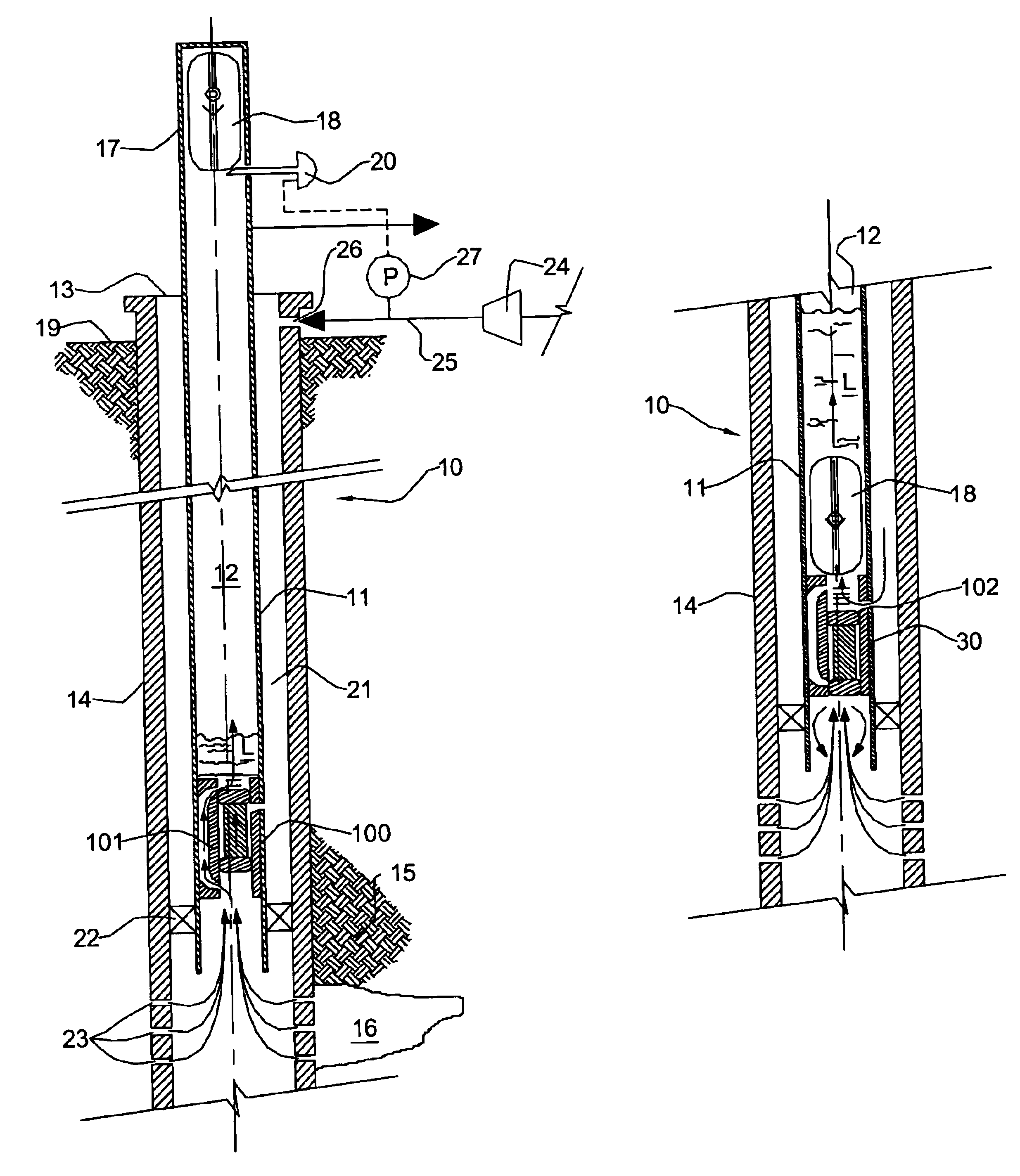
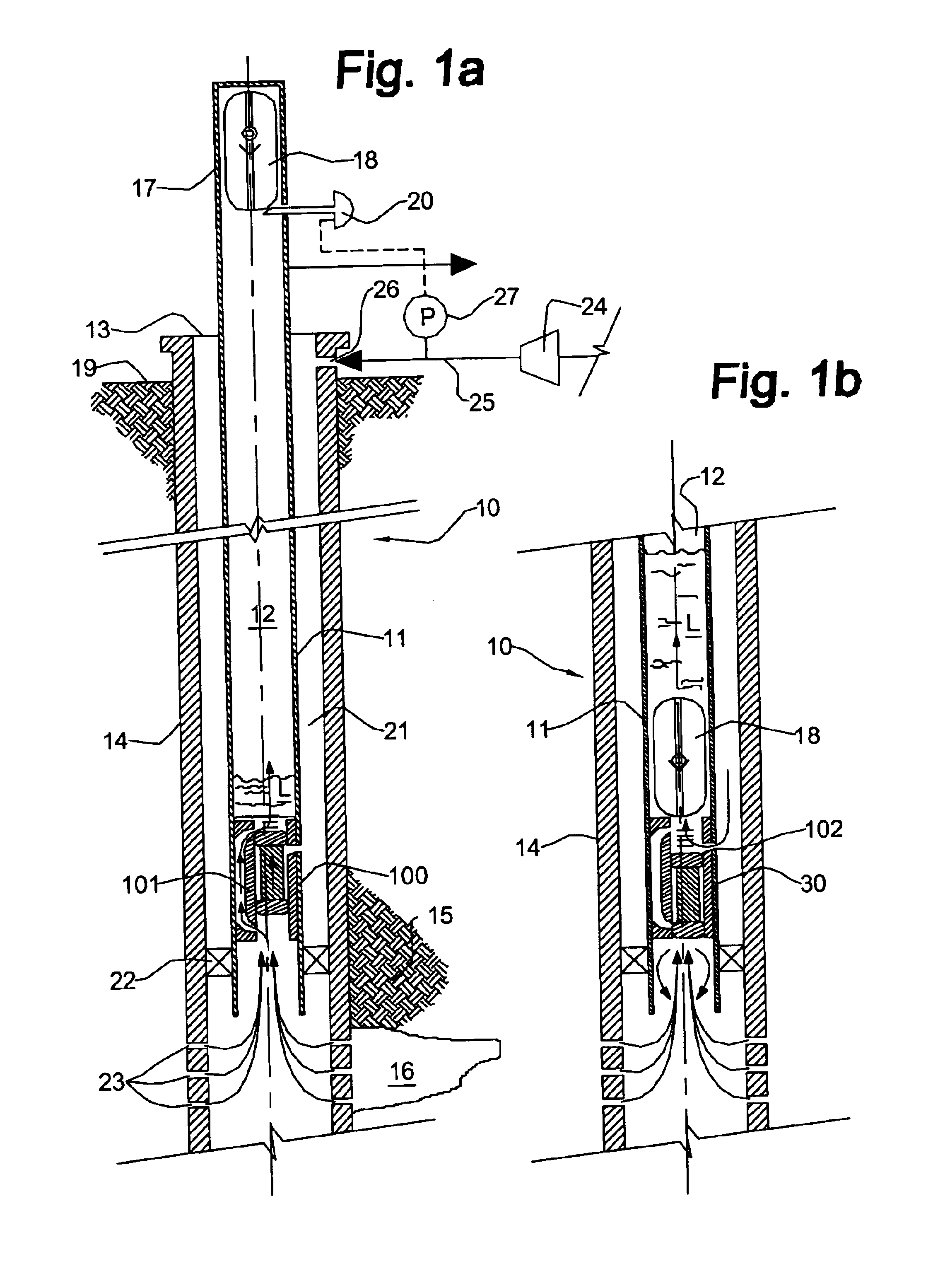
[0037]Having reference to FIGS. 1a-1b, a plunger-actuated gas lift production system 10, according to the present invention, is shown. The system typically comprises a tubing string 11 having a bore 12 and which extends downhole from a surface wellhead 13. The tubing string 11 extends down a wellbore having a casing 14 and into a formation 15 containing a hydrocarbon reserve or reservoir 16, under pressure.

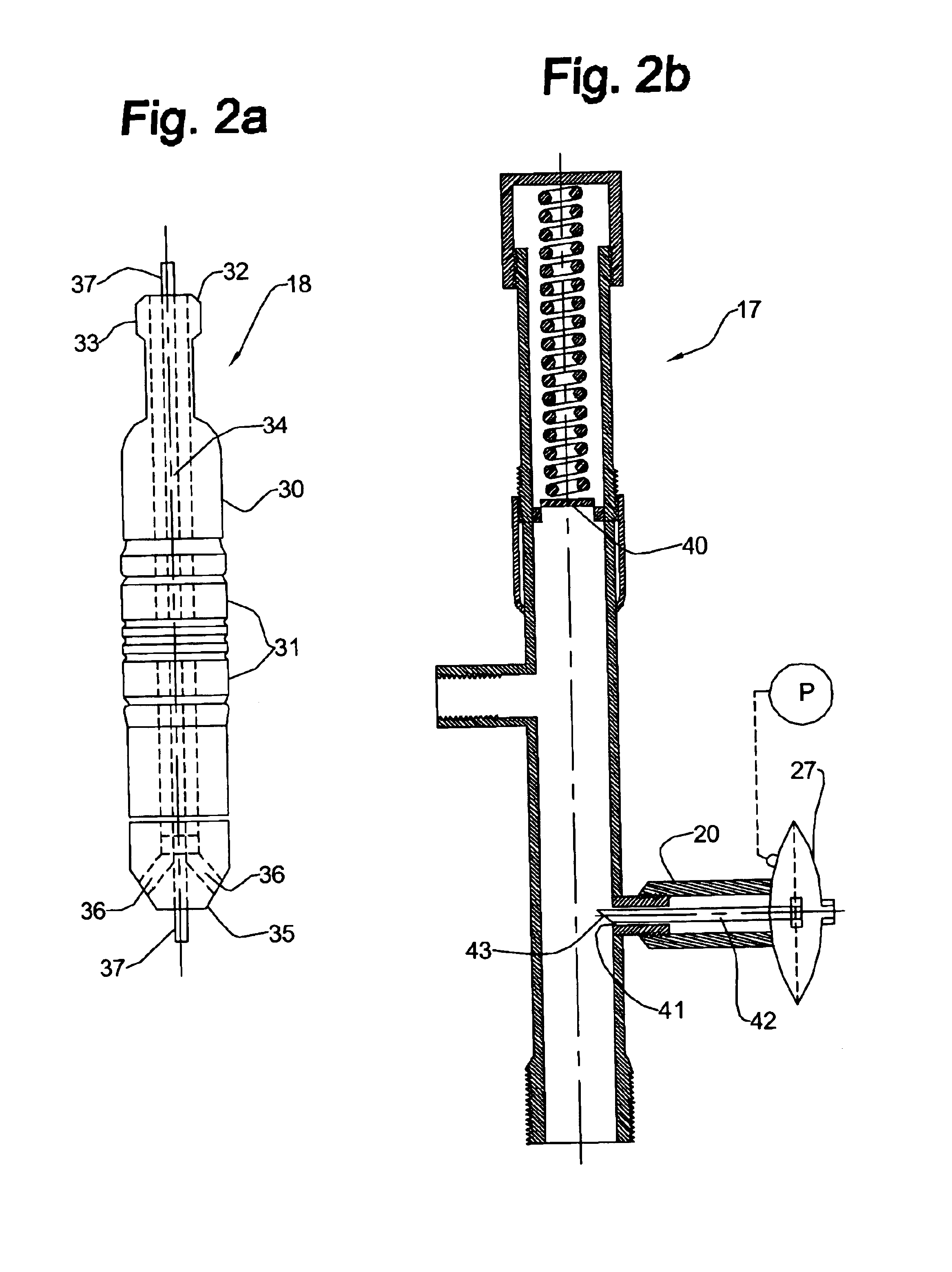
[0038]In a preferred embodiment of the invention, a conventional lubricator 17 and plunger 18, common to conventional plunger-lift systems, are connected to the tubing string 11 at surface 19. The plunger 18 is designed to free fall through the tubing string 11, but is designed to have tolerances sufficiently tight to create a liquid seal when being lifted up the tubing string 11. The plunger 18 is retained in the lubricator 17 by a catching mechanism 20 which is pneumatically controlled by the pressure in an annulus 21.

[0039]A conventional packer 22 is set in the wellbore between...


PUM


Abstract

A system is provided for unloading accumulated liquids and enhancing the recovery of gas from a reservoir having diminished pressure. An annulus between a tubing string and casing is isolated by a packer and continually pressurized with a slipstream of compressed gas while the well continues to produce. A unique valve positioned in the tubing string is shuttled between a production position in which production fluids are permitted to bypass the valve to the surface and a lift position in which the bypass is blocked and an unloading port is opened to vent high pressure annulus gas to the tubing string above the valve, lifting accumulated liquids with it. Preferably, the valve is actuated to the lift position by the impact of a plunger dropped from a lubricator at the wellhead, when the pressure in the annulus has reached a predetermined threshold. When the gas has been vented and the pressure in the annulus drops, the valve is actuated to the uphole production position as a result of the higher reservoir pressure.

Description

CROSS REFERENCE TO RELATED APPLICATION[0001]This application is a divisional application of U.S. patent application Ser. No. 09 / 948,647, filed Sep. 10, 2001 and issued on Mar. 16, 2004 as U.S. Pat. No. 6,705,404, the entirety of which is incorporated herein by reference.FIELD OF THE INVENTION[0002]The present invention relates to apparatus and methods for lifting liquids from a wellbore during production of gas or oil and more particularly to lifting liquids from wellbores where the natural reservoir pressure has diminished over time.BACKGROUND OF THE INVENTION[0003]It is well known that during the production of hydrocarbons, particularly from gas wells, the accumulation of liquids, primarily water, has presented great challenges to the industry. As the liquid builds at the bottom of the well, a hydrostatic pressure head is built which can become so great as to overcome the natural pressure of the formation or reservoir below, eventually “killing” the well.[0004]A fluid effluent, in...

Claims


Application Information

Patent Timeline
IPC IPC(8): E21B43/12
CPCE21B43/123E21B43/122
Inventor BOSLEY, GORDON F.
Owner G BOSLEY OILFIELD SERVICES
Why Eureka
Try Eureka