Automatic swing device

a technology of automatic swinging and swinging, which is applied in the direction of sofas, cycles, cycle equipment, etc., can solve the problems of possible malfunction, large power consumption, and noise generation of operation, and achieve the effect of simple structure and operation without malfunction

Inactive Publication Date: 2005-06-21
KUKUTOYS
View PDF10 Cites 37 Cited by
  • Summary
  • Abstract
  • Description
  • Claims
  • Application Information

AI Technical Summary

Benefits of technology

[0011]The present invention has been made to solve the above-mentioned problems occurring in the prior art, and an object of the present invention is to provide an electromagnetic type swing device having a simple structure and operating without malfunction.

Problems solved by technology

The electromotor type swing device has a drawback in that an operational noise is generated and power consumption is large because it is driven by a motor.
However, such electromagnetic type swing device has problems in that a structure is complicated and in that, if the photo sensor detects a wrong position of the seat, the polarity of the electromagnet is changed opposite to that of the permanent magnet so that a malfunction is possibly generated in which the seat is fixed on that position.

Method used


Image

  • Automatic swing device
  • Automatic swing device
  • Automatic swing device

Examples


Embodiment Construction

[0022]Hereinafter, the preferred embodiment of the present invention will be described in greater detail with reference to the accompanying drawings.

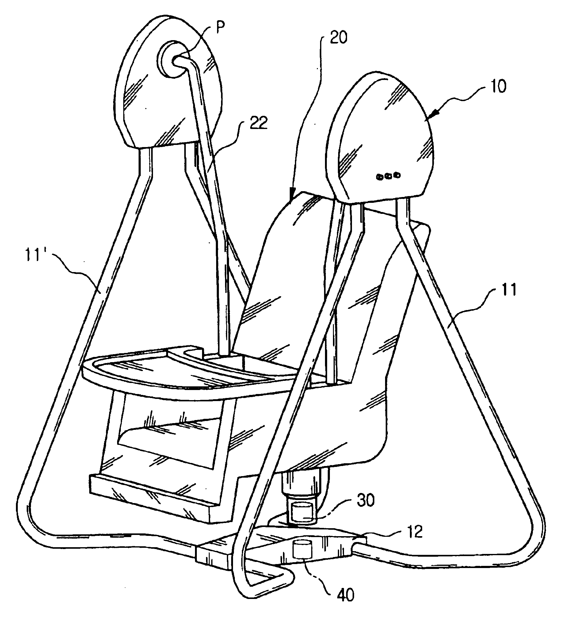
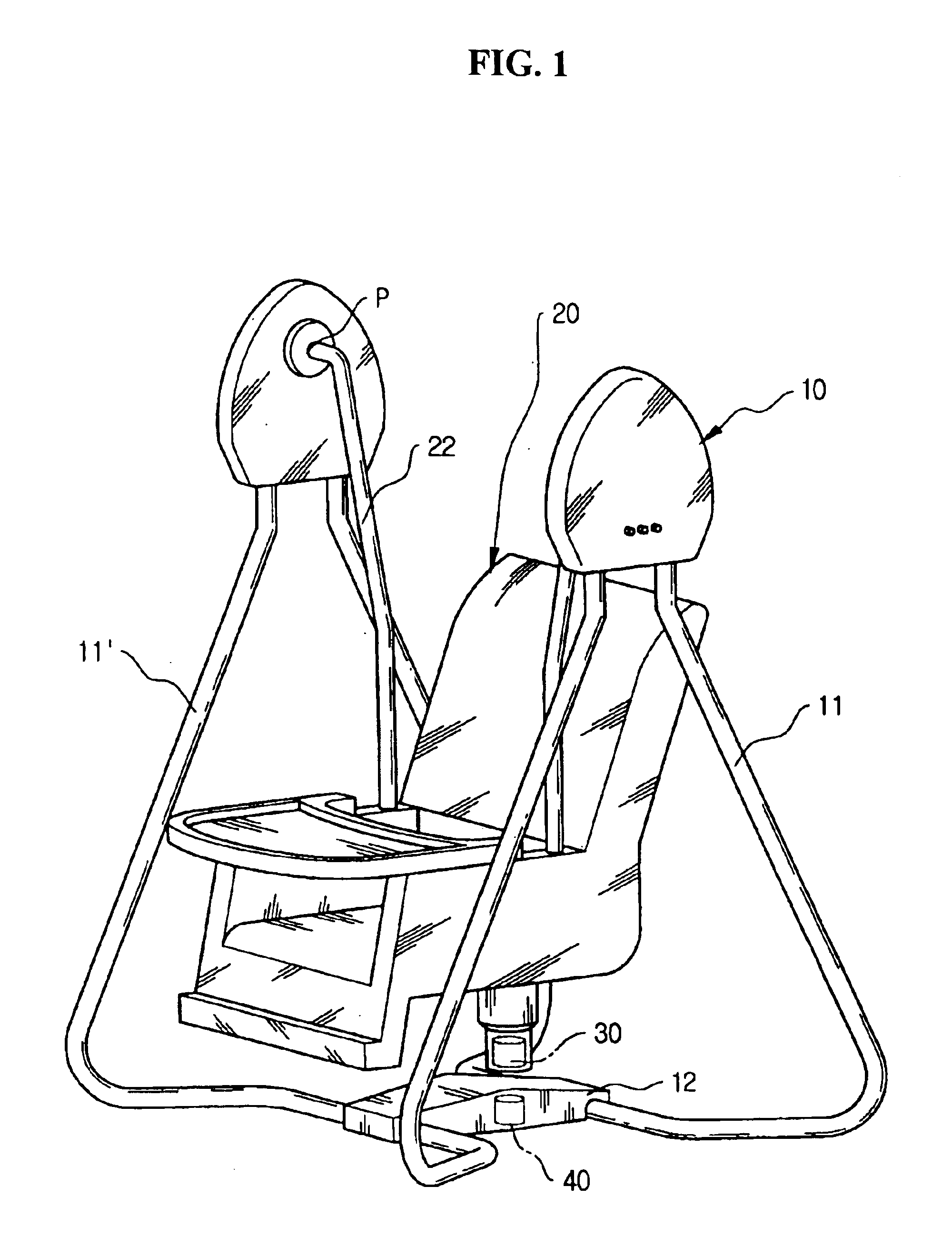
[0023]FIG. 1 is a perspective view of a swing device according to one embodiment of the present invention.

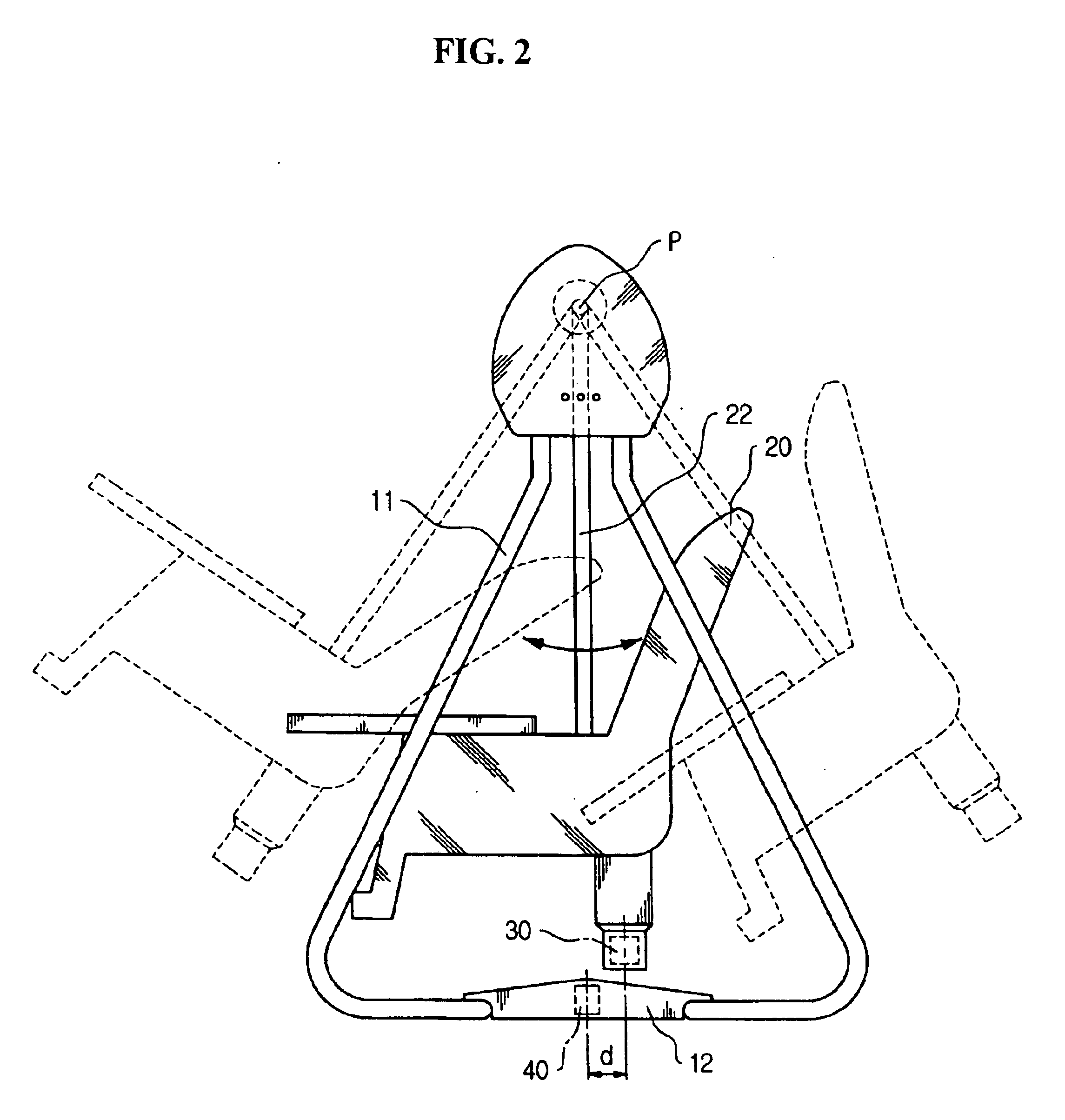
[0024]As shown in FIG. 1, a swing device of the present invention includes a supporter 10 and a seat 20 suspended on the supporter to swing in a front and back direction of the supporter. Particularly, the supporter 10 has a pair of triangular frames 11 and 11′ opposite to each other with a certain distance, and a supporting portion 12 connecting lower portions of the frames 11 and 11′. The seat 20 is swingingly connected to the upper portions of the frames 11 and 11′ by a pair of bars 22. That is, the lower portions of the bars 22 are coupled with the seat 20 and the upper portions of the bars 22 are rotatably coupled with the upper portions of the frames 11 and 11′ so that the seat 20 can be swung in the front and back side direct...


PUM


Abstract

A swing device has a supporter, a seat suspended on the supporter to swing in front and back directions, a permanent magnet installed in the seat, and an electromagnet installed to face the permanent magnet in a swing path to have the same polarity as that of the permanent magnet. The electromagnet is selectively driven when the permanent magnet approaches, generating a repulsive force for the permanent magnet. The seat swings by the repulsive force. The swing device has merits in that its simple structure makes manufacturing cost reduced and that a fixed polarity of the electromagnet prevents a malfunction of the device.

Description

CROSS-REFERENCE TO RELATED APPLICATIONS[0001]This application claims the benefit of Korean Patent Application No. 2004-270 filed on Jan. 5, 2004, in the Korean Intellectual Property Office, the disclosure of which is incorporated herein by reference.BACKGROUND OF THE INVENTION[0002]1. Field of the Invention[0003]The present invention relates to a swing device such as a swing or a cradle and so on, and more particularly to an automatic swing device capable of automatically swing using electromagnetic force.[0004]2. Description of the Prior Art[0005]Generally, a swing device such as a swing or a cradle and so on moving front and back has been widely used in order for a good sleep or a play for a baby. Particularly, recently, an automatic swing device has been developed which automatically swings using an external power.[0006]Such automatic swing device is classified into an electromotor type and an electromagnetic type in accordance with a driving manner thereof, wherein the electromo...

Claims


Application Information

Patent Timeline
Patent Type & Authority Patents(United States)
IPC IPC(8): A63G9/16A63G13/00A63G13/02A63G9/00A47D9/02A47D13/10
CPCA47D13/105A47D13/10A47D15/00H01F7/02H01F7/06Y10S297/11
Inventor KANG, SOON-DONG
Owner KUKUTOYS
Why Eureka
Try Eureka